105
Maintenance and Troubleshooting
15.3
TC sensor maintenance
15.3.1 Maintenance schedule
Service includes membrane replacement and external cleaning to restore the original sensor
sensitivity. This means low running costs and down time reduced to a minimum.
The membrane needs to be replaced once or twice a year depending on application conditions.
This can be tailored accordingly.
Note:
If you are not familiar with ORBISPHERE sensor servicing, your Hach representative will be glad to
assist you
15.3.2 Testing the sensor condition
Periodically, inspect visually the sensor head for any deposits. Rinse it under clean tap water,
and dry with a clean tissue.
To verify the sensor, check measurements vs. a known standard sample value:
•
If reading deviation is ±1% of the expected value, no action needs to be taken.
•
If deviation exceeds ± 1%, perform a new calibration.
•
If deviation exceeds 10% of the original values, replace the membrane.
15.3.3 Membrane replacement
To remove the membrane, follow the steps below:
1.
Place the thermal conductivity sensor vertical with the head up. Remove the plastic storage
cap.
2.
Unscrew the protection cap, using the tool provided in the maintenance kit.
3.
Pay attention to the components inside the protection cap. Refer to
caps and related part kits on page 113
. Note the assembly order of each item.
Note:
The illustration is an example only. Your configuration may differ.
4.
Pull up the membrane holding ring with the tool provided in the maintenance kit. Remove
membrane(s).
Note:
For correct membrane selection. Refer to
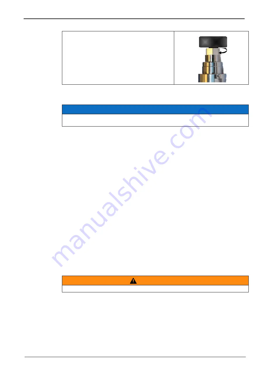
4.
Turn the tool clockwise to screw in the new sensor
spot, finger tight. Do not overtighten. Once secure,
pull off the maintenance tool.
N O T I C E
Carry out the maintenance in a clean dry place in order to avoid damaging the sensor's
precision components, and also to prevent water or humidity from getting into the sensor.
C A U T I O N
Never remove the protection cap, unless you plan to replace the membrane.
Summary of Contents for Orbisphere 51 Series
Page 5: ...4 Table of Contents...
Page 19: ...18 Specifications...
Page 48: ...47 Section 6 View Menu Figure 33 View menu...
Page 52: ...51 Section 7 Measurement Menu Figure 36 Measurement menu...
Page 66: ...65 Section 9 Inputs Outputs Menu Figure 40 Inputs Outputs menu...
Page 68: ...67 Inputs Outputs Menu 9 4 Analog outputs Figure 41 Analog outputs menu...
Page 75: ...74 Inputs Outputs Menu...
Page 91: ...90 Communication Menu...
Page 94: ...93 Section 12 Products Menu Figure 44 Products menu...
Page 97: ...96 Global Configuration Menu...
Page 98: ...97 Section 14 Services menu Figure 46 Services menu Part 1...
Page 99: ...98 Services menu Figure 47 Services menu Part 2...
Page 103: ...102 Services menu...


