106
Maintenance and Troubleshooting
To install the new membrane(s), follow the steps below:
1.
Replace the membrane O-ring on the sensor head with a new one.
Note:
The membrane mounting surface must be clean and even (on top of the sensor, where the
membrane and sensor have contact).
Note:
The 29039.0 Nitril O-ring can be reused if it is still in good condition. Membrane O-rings are part of
the protection cap kit.
2.
In the maintenance kit, pick up the two part membrane mounting tool. Install the sleeve over
the sensor head (end with shoulder downwards).
Note:
Once installed, a membrane cannot be reused. Avoid touching the membrane with bare fingers, as
this may affect its sensitivity.
3.
Take a few membranes out of the storage box. Using tweezers included in the kit, pick up
one membrane from the stack, and gently place it on the sensor tip. Make sure it is
centered. The membrane diameter is larger than the sensor head diameter. This is normal,
as the membrane will fold over the sensor tip.
Note:
Distinguish the membrane from the protection paper:
- Membrane is transparent (translucent).
- Protection paper is opaque.
4.
Place the membrane holding ring on installation tool tip.
5.
Insert the installation tool inside the guiding sleeve.
6.
Push the installation tool firmly downwards. This clasps the mounting ring onto the sensor
head, folding the membrane(s) over the sensor tip. Remove the installation tool and guiding
sleeve. Visually check for correct ring placement, try to push it down with your fingers.
Check that the membrane is tight, with no wrinkles.
Once installed, a membrane cannot be reused. Avoid touching membranes with bare fingers, as this may
affect its sensitivity.
7.
Prepare the protection cap for installation. All parts must be absolutely dry and clean.
Replace all the parts inside the protection cap with new ones (except the grille), and place
them in the order they were removed. The Tefzel washers, under the cap, should be slightly
lubricated with silicone grease.
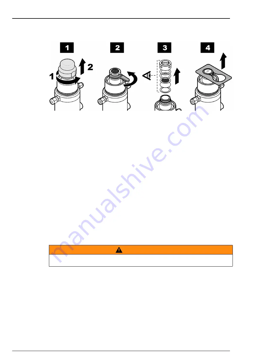
The illustration is an example only. Your configuration may differ.
Figure 48 Removing the membrane
C A U T I O N
To avoid damaging the membrane, make sure that the tool tip is totally clean and its
surface is even.
Summary of Contents for Orbisphere 51 Series
Page 5: ...4 Table of Contents...
Page 19: ...18 Specifications...
Page 48: ...47 Section 6 View Menu Figure 33 View menu...
Page 52: ...51 Section 7 Measurement Menu Figure 36 Measurement menu...
Page 66: ...65 Section 9 Inputs Outputs Menu Figure 40 Inputs Outputs menu...
Page 68: ...67 Inputs Outputs Menu 9 4 Analog outputs Figure 41 Analog outputs menu...
Page 75: ...74 Inputs Outputs Menu...
Page 91: ...90 Communication Menu...
Page 94: ...93 Section 12 Products Menu Figure 44 Products menu...
Page 97: ...96 Global Configuration Menu...
Page 98: ...97 Section 14 Services menu Figure 46 Services menu Part 1...
Page 99: ...98 Services menu Figure 47 Services menu Part 2...
Page 103: ...102 Services menu...


