33
Installation
3.8
Sensor installation
3.8.1
Purge gas system for the TC sensor
To ensure the continuation of purge gas while the sensor is in contact with the sample, it is
highly recommended to use a backup purge gas cylinder with an automatic changeover valve
that activates when the first cylinder is empty.
The use of an ORBISPHERE Model 29089 gas regulator (or similar) is also recommended to
deliver a constant, pressure regulated supply of dry purge gas to the sensor, filtered to 40 µm.
In addition, and to prevent any damage to the sensor electronics, the use of a purge safety
backup unit (ORBISPHERE Model 32605) is highly recommended to ensure the supply of purge
gas remains uninterrupted to the sensor in the event of a mains power outage.
3.8.1.1 Purge gas regulator
3.8.1.2 Purge gas supply
Note:
Check the purge gas specifications. Refer to
TC sensor purge gas pressure regulator on page 14
.
Make sure there is no interruption in the purge gas supply. The use of a backup gas cylinder
and an automatic changeover valve, that activates when the first cylinder is empty, are
recommended.
Use a 6 mm flexible (nylon or PVC) or rigid (stainless steel) line to connect the pressure
regulator and thermal conductivity sensor to the purge gas supply. Swagelok connectors (6 mm
or 1/4") are provided.
A short length of plastic tube is supplied for the purge gas to exit the sensor. To insert, push the
tube firmly into the orifice. To remove, push on the ring surrounding the tube, and pull the tube
out. For certain applications such as waste gas, a 3 mm (1/8") Swagelok fitting is provided for
the purge gas exit, to enable safe evacuation of an eventually hazardous gas.
N O T I C E
Do not place the TC sensor into a liquid sample until a constant supply of dry purge gas has
been connected, as liquid could condense inside the measuring chamber and cause damage
to the thermal conductor chip.
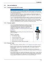
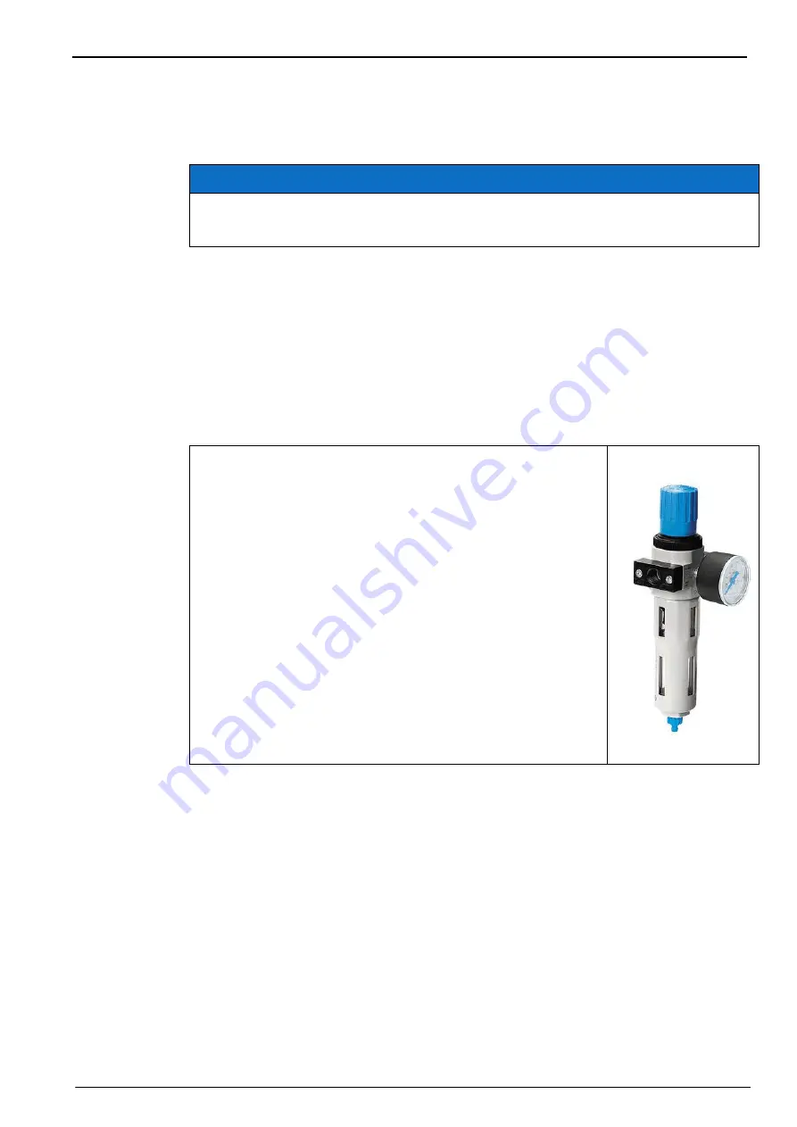
The role of the ORBISPHERE 29089 gas regulator is to deliver
purge gas filtered at 40 µm. Attach the unit to a suitable bracket,
using the M3 threaded holes on the back. It’s position should be
vertical ± 5%. The gas flow is indicated by an arrow on the
regulator's body. Refer to
TC sensor purge gas pressure regulator
Maintenance:
Drain the condensate periodically. Unscrew by hand the drain at the
bottom of the bowl.
If filter is contaminated:
•
Turn off the gas supply
•
Unscrew the bowl by hand
•
Unscrew the black disc at the bottom
•
Remove the white composite filter
•
Wash under clean tap water, blow dry, and install
Summary of Contents for Orbisphere 51 Series
Page 5: ...4 Table of Contents...
Page 19: ...18 Specifications...
Page 48: ...47 Section 6 View Menu Figure 33 View menu...
Page 52: ...51 Section 7 Measurement Menu Figure 36 Measurement menu...
Page 66: ...65 Section 9 Inputs Outputs Menu Figure 40 Inputs Outputs menu...
Page 68: ...67 Inputs Outputs Menu 9 4 Analog outputs Figure 41 Analog outputs menu...
Page 75: ...74 Inputs Outputs Menu...
Page 91: ...90 Communication Menu...
Page 94: ...93 Section 12 Products Menu Figure 44 Products menu...
Page 97: ...96 Global Configuration Menu...
Page 98: ...97 Section 14 Services menu Figure 46 Services menu Part 1...
Page 99: ...98 Services menu Figure 47 Services menu Part 2...
Page 103: ...102 Services menu...

