34
Installation
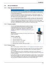
A source of dry and filtered gas (pure at 99.8%) is required with a flow rate set at 10 to 50
ml/min., and a pressure regulated at 2 bar gauge. Do not exceed this, since excess pressure
will deform the membrane and change measurements.
To check the flow rate, put the exit tube into a cup of water. With the instrument turned on, you
should see at least three bubbles per second during the purge cycle (or select the "Continuous
Purge" function in the instrument "Options" menu).
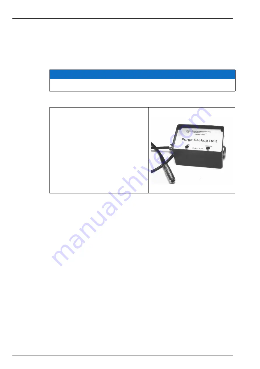
3.8.1.3 Purge gas backup unit
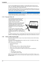
The 32605 purge backup unit is connected between the instrument and the sensor. The internal
batteries are automatically charged through the sensor cable when the instrument is turned on.
3.8.2
Sensor positioning information
The sensor must be installed in a socket or flow chamber that allows contact with the sample
fluid to be analyzed.
The sensor and measuring instrument are connected by a cable. The standard sensor cable
lengths are 3, 5, 10, 15 and 20 meters.
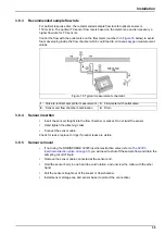
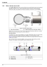
Ensure that the sensor will be mounted:
•
perpendicular to the pipe
•
horizontal
•
on a horizontal pipe section (or on flow-ascending vertical pipe)
•
minimum of 15 meters away from the pump's discharge side
•
in a place where the sample flow is stable and rapid, and as far as possible from:
•
valves
•
pipe bends
•
the suction side of any pumps
•
a CO
2
injection system or similar
Note:
There may be situations where not all the above conditions can be met. If this is the case, or you
have any concerns, please consult your Hach representative to appraise the situation and define the best
applicable solution.
N O T I C E
Potential Sensor Damage. Do not leave the exit tube in water, as there is a risk that moisture
will get sucked back into the sensor and damage it.
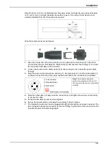
The gas analyzer must be switched on at all
times, and purge gas must be constantly
supplied to purge the sensor cell, to prevent
damage to the sensor electronics.
However, in the event of a mains power outage,
the 32605 purge backup unit ensures that the
purge gas supply to the TC sensor is not
interrupted at any time. The cycle is slower than
usual (around one minute), for approximately
four days.
The green LED is on as long as the battery
charge is OK. The red LED is on when charging
is needed. To save batteries, both LEDs are out
when the backup unit is in use, and mains power
is out.
Summary of Contents for Orbisphere 51 Series
Page 5: ...4 Table of Contents...
Page 19: ...18 Specifications...
Page 48: ...47 Section 6 View Menu Figure 33 View menu...
Page 52: ...51 Section 7 Measurement Menu Figure 36 Measurement menu...
Page 66: ...65 Section 9 Inputs Outputs Menu Figure 40 Inputs Outputs menu...
Page 68: ...67 Inputs Outputs Menu 9 4 Analog outputs Figure 41 Analog outputs menu...
Page 75: ...74 Inputs Outputs Menu...
Page 91: ...90 Communication Menu...
Page 94: ...93 Section 12 Products Menu Figure 44 Products menu...
Page 97: ...96 Global Configuration Menu...
Page 98: ...97 Section 14 Services menu Figure 46 Services menu Part 1...
Page 99: ...98 Services menu Figure 47 Services menu Part 2...
Page 103: ...102 Services menu...

