


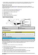

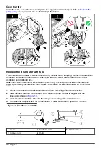
Figure 8 Controller connectors
1
Auxiliary device
4
SDI-12 device option
2
Power supply
5
Distributor/full bottle shut-off
3
Serial communications
Connect a flow meter
Connect a flow meter to the controller to start or stop the sampler when the sample flow goes above
or below a specified value.
Items to collect:
• Multi-purpose full cable for Sigma flow meters (or 980 half cable for the model 980 flow meter).
• Optional splitter for additional connections. Two or more splitters can be connected in series.
1.
Connect one end of the cable to the flow meter. For the model 980 flow meter, refer to the model
980 flow meter user manual.
2.
Connect the other end of the cable to the auxiliary device connector on the controller.
Note: If the flow meter has a 6-pin cable, use the 6-pin to 7-pin adapter cable.
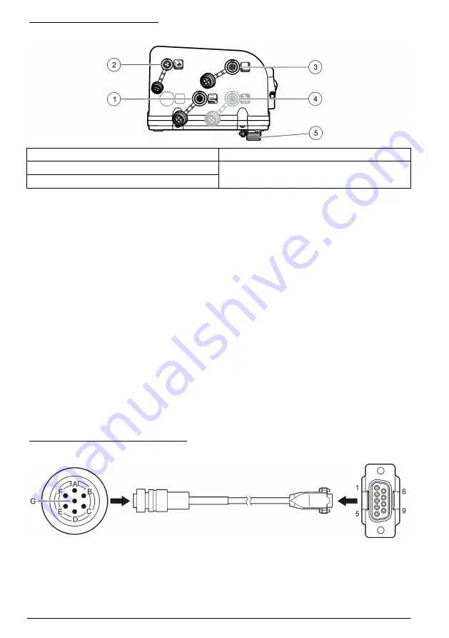
Connect a PC or communications network
Connect a PC or a communications network to the controller to transfer data or to configure the
sampler.
Items to collect:
• Serial cable, 7-pin RS232 to DB-9 (refer to
). Connections: B to 5 (signal ground); D to
3 (RCD); F to 2 (TXD); G (ground).
1.
Connect one end of the serial cable to the communications device or network.
2.
Connect the other end of the cable to the serial communications connector on the controller.
Figure 9 Serial communications cable
14
English
Summary of Contents for SD900
Page 2: ...English 3 Fran ais 28 Espa ol 54 Portugu s 80 106 129 153 2...
Page 25: ...English 25...
Page 103: ...Portugu s 103...
Page 109: ...FCC 15 A 1 2 3 4 5 SD900 1 1 1 6 2 7 3 8 4 9 5 10 21 L 5 5 gal 2 109...
Page 111: ...110 106 111 114 106 1 111 2 3 111...
Page 113: ...4 1 1 1 6 2 1 24 7 21 L 5 5 gal 3 1 8 8 4 1 2 4 9 5 1 111 2 1 112 3 5 8 4 8 113...
Page 115: ...6 1 3 2 7 8 115...
Page 117: ...15 A 117 1 2 10 3 117...
Page 118: ...10 50 C 122 F 1 3 5 15 2 11 MENU ENTER BACK 118...
Page 125: ...12 1 12 2 3 4 5 O 6 12 1 3 O 2 4 125...
Page 126: ...4 6 m 15 2 m 15 ft 50 ft 1 2 3 4 5 126...
Page 127: ...126 127...
Page 128: ...1 2 13 3 4 13 1 3 5 2 4 128...
Page 131: ...Web IECS 003 A 131...
Page 133: ...1 1 6 2 7 3 8 4 9 5 10 21 L 2 HACH Japan 2 1 6 2 7 AC 3 8 4 9 5 10 133...
Page 136: ...1 5 137 4 1 1 1 6 2 1 24 7 21 L 3 1 8 8 4 2 2 4 9 5 1 135 2 1 135 3 5 8 1 4 8 136...
Page 138: ...6 1 3 2 7 8 138...
Page 140: ...GFCI GFI 15 A PE 141 AC 140...
Page 141: ...1 2 10 3 10 50 C 1 3 5 15 2 AC 11 MENU ENTER BACK 141...
Page 149: ...12 1 12 2 3 4 5 O 6 12 1 3 O 2 4 149...
Page 150: ...4 6 m 15 2 m 1 2 Web 3 4 5 150...
Page 151: ...150 151...
Page 152: ...1 2 13 3 4 13 1 3 5 2 4 152...
Page 155: ...IECS 003 A 155...
Page 157: ...1 1 6 2 7 3 8 4 9 5 10 21 L 5 5 gal 2 2 1 6 2 7 AC 3 8 4 9 Teflon 5 10 157...
Page 158: ...XXX 1993 4 15 OSHA CFR 1910 146 250 000 19 5 23 5 H2S 10 ppm 158 153 159 161 153 158...
Page 160: ...4 1 1 1 6 2 24 1 7 21 L 5 5 gal 3 8 1 8 4 2 4 1 9 5 1 159 2 1 159 3 5 8 1 4 8 160...
Page 162: ...6 1 3 2 7 8 162...
Page 164: ...GFCI GFI 15 A PE 165 AC 164...
Page 165: ...1 2 10 3 10 50 C 122 F 1 3 5 15 2 AC 11 MENU ENTER BACK 165...
Page 172: ...0 1 MANUAL OPERATION 2 GRAB SAMPLE 3 4 5 6 7 ENTER 8 172...
Page 173: ...12 1 12 2 3 4 5 6 12 1 3 2 4 4 6 m 15 2 m 15 ft 50 ft 1 2 3 4 5 173...
Page 174: ...174...
Page 175: ...173 1 2 13 3 4 13 1 3 5 2 4 175...
Page 176: ......
Page 177: ......


