5.52.653.01.01.04
13
6.3.1
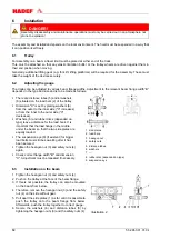
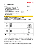
Bolt securing with collar
Securing the load bolts with set collars (1) and safety
screws (3).
In order to adjust the beam flange width dismantle
the safety screws (3) at one trolley side.
After adjustment of dimension "X" and installation on
the beam, install the safety screws (3) again and
secure them with a nut (4).
When pulling apart the side plates, the trolley drive
shaft will also be moved.
To do this, loosen the safety screws at the stern tube
bearing and secure them again after the side plates
have been pushed together.
Illustration 3
1 set collar
2 load bar
3 safety screw
4 hexagon nut
5 washer
CAUTION!
The distance “X” between the wheel flanges of the trolley wheels must be
for trolleys up to 3,2 t: 2-3 mm (1-1,5 mm each side) bigger and
for trolleys from 4 t up: 3-5 mm (1,5-2,5 mm each side) bigger than the flange width "B" of the beam
6.4
Tools
7
Control
Only people that are familiar with the operation of the lifting devices and cranes may be entrusted with their
operation. They must be authorized by the employer for the operation of the equipment. The employer must
ensure that the operating instructions are available near the equipment and that they are accessible for the
operating personnel.
Monorail push travel trolleys are moved by pushing the load.
Monorail hand geared trolleys are moved by pulling the hand chain.
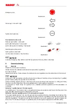
Control buttons
Control symbols shown are for optical information only and can vary depending on the control module.
Capacity
Size
Tool
Use
0,5t
1t
to 2t
to 3,2t
to 6,3t
to 10t
SW27
SW36
SW46
SW55
SW60
SW75
Load bar
12,5t
to 60t
SW22
SW24
Load bar
with
fixing ring
diff.


