background image


5.52.162.00.01.05 


6.2 

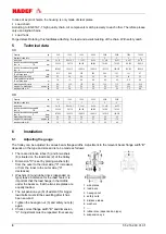
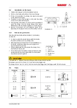
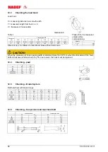
Installation on the beam 

1  Tighten the hexagon nut (3) and safety nuts (4). 

2  Push on the trolley at the face of the beam flange. 

3  If  this  is  not  possible,  the trolley  can  also  be  mounted 

on the beam from below. 

4  Therefore, remove the hexagon nut (3) and the safety 

nut (4) on the side without gear. 

5  Pull apart the side plates (1) as far until it is possible to 

push  the  trolley  onto  the  beam  flange  from  below. 
Afterwards, push the trolley together to correct gauge. 

6  Secure  the  washers  (6)  and  distance  tubes  (5)  by 

tightening the hexagon nuts (3) and the safety nuts (4). 


Illustration 3 


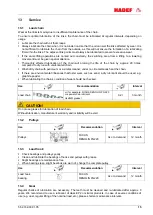
6.2.1 

Bolt securing with collar 

Securing the load bolts with set collars (1) and safety 
screws (3). 


  In order to adjust the beam flange width dismantle 

the safety screws (3) at one trolley side. 

  After adjustment of dimension "X" and installation on 

the beam, install the safety screws (3) again and 
secure them with a nut (4). 

  When pulling apart the side plates, the trolley drive 

shaft will also be moved. 

  To do this, loosen the safety screws at the stern tube 

bearing and secure them again after the side plates 
have been pushed together. 


Illustration 4 


1  set collar 

2  load bar 

3  safety screw 

4  hexagon nut 

5  washer


CAUTION!


The distance 

“X” between the wheel flanges of the trolley wheels must be 

for trolleys up to 3,2 t: 2-3 mm (1-1,5 mm each side) bigger and 

for trolleys from 4 t up: 3-5 mm (1,5-2,5 mm each side) bigger than the flange width "B" of the beam 


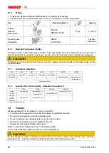
6.3 

Tools 


Capacity 

Size 

Tool 

Use 


0,5t 

1t 

to 2t 

to 3,2t 

to 6,3t 

to 10t 

SW27 

SW36 

SW46 

SW55 

SW60 

SW75 


Load bar 


12,5t 

to 60t 

SW22 

SW24 


Load bar  

with 

fixing ring 


diff. 


Summary of Contents for 21/12

Page 1: ...5 52 162 00 01 05 Rev 05 HADEF Spur Gear Chain Hoist Type 21 12 with monorail push travel trolley HR with monorail hand geared trolley HH Installation Operating and Maintenance Instructions...

Page 2: ...nges Table of Contents 1 Information 3 2 Safety 4 2 1 Warning notice and symbols 4 2 2 Duty of care of the owner 4 2 3 Requirements for the operating personnel 5 2 4 Appropriate use 5 2 5 Basic safety...

Page 3: ...to a certified quality assurance system as per ISO 9001 The production of components at our work is subject to strict intermediate checks After assembly each product is subject to a final test with ov...

Page 4: ...or they must be suitable for use in area prone to explosion The owner is responsible for this However in everyday operation this degree of safety can only be achieved if all measures required are take...

Page 5: ...iginal spare parts must be used Non compliance will result in any warranty claims becoming void Liability and warranty will become void if unauthorized modifications of the units are made by the user...

Page 6: ...wisted chains must be aligned before attaching the load The correct alignment of the chain links can be seen from the weld seams The chain links must always be aligned in one direction Don t bump agai...

Page 7: ...the unit in an area at risk from explosion 4 2 Design HADEF Spur Gear Hoists of compact design are monorail trolleys combined with manual hoists With monorail push travel trolley or with monorail han...

Page 8: ...ain falls 1 1 1 1 2 2 Load chain mm 5 x 15 6 3 x 19 1 7 1 x 21 8 x 24 7 1 x 21 9 x 27 Load bar size at beam flange width from to 1N mm 50 146 50 179 66 185 66 185 74 196 74 192 Load bar size at beam f...

Page 9: ...to adjust the beam flange width dismantle the safety screws 3 at one trolley side After adjustment of dimension X and installation on the beam install the safety screws 3 again and secure them with a...

Page 10: ...s the lowering operation must be carried out without load at certain intervals until both chain container are empty For motorized devices with operating limit switches lowering Lower until the operati...

Page 11: ...uthorities Z S 8 2 Load chain Before commissioning the load chain must be aligned and oiled For the first commissioning of motorized hoists chain oil is supplied with the delivery Move safety note and...

Page 12: ...insert new chains in an unloaded state and as the chains that are currently in the device i e not twisted Remove chain from its fastening at the end and attach a chain link which is open at the side...

Page 13: ...the table or if cracks or corrosion are found the parts must be replaced with original spare parts 12 2 Checking the load chain CAUTION The load chain must be tested over its entire length The measur...

Page 14: ...hen the dimension of hook opening width is deformed more than 10 or when the dimension of the hook bottom thickness is fallen short of by 5 due to wear the hook must be replaced 12 4 Checking pawl A V...

Page 15: ...e chain If there are environmental influences that foster wear such as sand a dry lubricant should be used e g graphite powder When lubricating the chain s condition of wear should be checked CAUTION...

Page 16: ...OBIL CASTROL KL BER Gearing FM Grease HD2 Mobilgrease FM 222 Kl beroil 4UH 1 1500 N Load chain Lubricant FM 100 Optimol Viscoleb 1500 Load hook Pulleys Gear rim Drive pinion FM Grease HD2 Mobilgrease...

Page 17: ...housing and got stuck there Release the hook suspend the load again lower the load unload the hoist Hoist does not lower the load Brake too tight Lift the brake Brake too tight due to rust Replace ru...

Reviews: