background image


12 


5.52.208.01.01.02 


Winches with separating partition 

Capacity 

FEM 

group 

wir-

erope 

Ø 


2x 

nec. 

minimum 

breaking 

load 

2x 

useable 

wire rope length 


2x 

number of 

rope layers 


2x 

wire rope 

path per 

crank turn 

crank 

effort 

weight 

without rope 

approx. 

1st layer 

top layer 


1st layer 

top layer 


kg 

kg 

1 Cm 

mm 

kN 


mm 

daN 

kg 

2 x 125 

2 x 45 

1 Cm 

4,5 

80 

16 

17 

13,5 

2 x 250 


2 x 110 

1 Cm 

76 

13 

20 

10 

16,5 

2 x 500 

2 x 265 

1 Cm 

17 

55 

13 

13 

27,5 

2 x 750 

2 x 400 

1 Cm 

34 

32 

14 

28,5 

2 x 1000 

2 x 525 

1 Cm 

34 

60 

12 (6) 

22 (12) 

62 

2 x 1500 

2 x 785 

1 Cm 

10 

51 

70 

11 (6) 

27 (14) 

80 

2 x 2500 

2 x 1540 

1 Cm 

12 

79 

50 

12 (4) 

58 (17) 

119 

() with crank changed in position 


Installation 


Please observe the following points in order to avoid any damage to equipment or injury of person: 

  Wear safety gloves. 

  Install the winch on a stable ground. 

  Make  sure  attachment  surface  is  flat  and  that  installation  is  made  stress-free,  -  use  shim  parts  if 

necessary. 

  The winch must be set up and attached in such a way that it cannot change position neither by the load 

nor by other influences. 


  The  winch  must  always  be  aligned  with  the  horizontally  adjusted  drum,  regardless  of  the  installation 

position  


6.1 

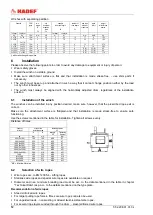
Installation of the winch 

The  winches can be  installed  in  any position  desired, make sure, however, that the prescribed  rope exit is 
correct. 

Make  sure  the  attachment  surface  is  flat/plain  and  that  installation  is  made  stress-free  to  ensure  safe 
functioning. 

Use the screws mentioned in the table for installation. Tighten all screws evenly. 

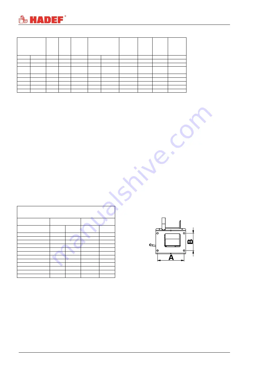
Distance of holes 


Capacity 

1st layer 

holes of the 

installation area


fastening screws 

4x


strength 

 8.8 

Tightening 

moment 

kg 

mm 

mm 


Nm 

250 (2x125) 

192 

100 

M12 

87 

500 (2x250) 

223 

115 

M12 

87 

1000 (2x500) 

254 

141 

M12 

87 

1500 (2x750) 

254 

178 

M12 

87 

2000 (2x1000) 

360 

196 

M20 

431 

3000 (2x1500) 

386 

251 

M20 

431 

5000 (2x2500) 

386 

316 

M20 

431 

7500 

455 

350 

M20 

431 

*MV 1500 

165 

210 

M16 

214 

*MV 3000 

446 

251 

M20 

431 

*MV 5000 

456 

316 

M20 

431 

*MV = Marine-Version 


6.2 

Selection of wire ropes 


  Wire ropes acc. to EN 12385-4 - Lifting ropes 


  Stainless wire ropes and special wire ropes are available on request. 

  Diameter  and  nec.  minimum  breaking  load  must  be  acc.  to  the  data  mentioned  in  the  table  in  chapter 

"Technical Data" resp. acc. to the details mentioned on the type plate. 

Recommendation of wire ropes 

  Steel-reinforced wire ropes 

  For larger pulling rope forces, fibre-core wire ropes can also be used. 

  For unguided loads, - non-twisting or at least twist-resistant wire ropes. 

  For several rope layers winded through the drum, - steel-reinforced wire ropes. 

Summary of Contents for 238/10-EX

Page 1: ...ch 238 10 EX Explosion proof design II 3G Ex h IIC T4 Gc 20 C Tamb 70 C or II 3D Ex h IIIC T135 C Dc 20 C Tamb 70 C DANGER The devices may only be operated in the area of the specified explosion protection class Installation Operating and Maintenance Instructions ...

Page 2: ...rning notice and symbols 3 2 2 Duty of care of the owner 4 2 3 Requirements for the operating personnel 4 2 4 Appropriate use 5 2 5 Basic safety measures 6 2 6 Explosion protection 7 3 Transport and Storage 9 3 1 Transport 10 3 2 Safety device for transport 10 3 3 Storage 10 4 Description 10 4 1 Areas of application 10 4 2 Design 10 4 3 Functions 11 4 4 Important components 11 5 Technical data 11 ...

Page 3: ...lation standards and regulations and is classified in the applicable Ex protection class The stated performance of the devices and meeting any warranty claims require adherence to all instructions in this manual Before delivery all products are packed properly Check the goods after receipt for any damage caused during transport Report any damage immediately to the forwarding agent This manual serv...

Page 4: ...o plan these measures and to check that they are being complied with Complete the operating and installation instructions by any instructions regarding supervision or notifications that are important for the special kind of use of the equipment i e regarding organization of work work flow and human resources In particular the owner user must ensure that The unit is only used appropriately The devi...

Page 5: ...ure range from 0 8bar to 1 1bar and an oxygen content of approx 21 DANGER The permissible ambient temperature must not be exceeded Vertical lifting and lowering of unguided loads horizontal movement of loads and inclined movement of loads movement of flaps covers etc 2 4 1 Winches with disengaging clutch as option Only for pulling out the uncharged wire rope Only for horizontal load Only for speci...

Page 6: ...t into motion any persons in the immediate vicinity must be informed by calling to them Please pay attention to the regulations for load carrying devices UVV for both positive and non positive methods of attaching loads The lifting tackle or the load must be securely attached to the hook and be seated at the bottom of the hook The safety catch of hooks must be closed When charged the housing may n...

Page 7: ...ation belonging to the unit is indicated on the type plate which is attached to the unit Example of ATEX classification II 2 G Ex h IIB T4 Gb CE marking European Union explosion proof operating material II device group application I II danger of mine damp other areas prone to explosion 2 device category 1 2 3 for use in zone 0 for use in zone 1 for use in zone 2 G EX atmosphere G D caused by gas s...

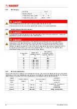
Page 8: ...s air mixtures for T5 do not occur with normal use and only very rarely occur for T6 for specific gas air mixtures such as carbon disulphide IIC our hoists are not rated for these temperature classes and must not be used for these classes Temperature class Ignition tem perature of gas C max surface temperature of the operating material in C T1 450 450 T2 300 450 300 T3 200 300 200 T4 135 200 135 T...

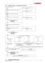
Page 9: ...5 52 208 01 01 02 9 2 6 4 Explosion hazards recognizing and preventing 3 Transport and Storage ...

Page 10: ...vered room If they are used in the open protect the units against the effects of weather such as rain hail snow direct sunshine dust etc we recommend to use a cover in parking position If the device is set up in a continuously humid environment with strong temperature fluctuations the correct functionings are endangered by the forming of condensation NOTICE Use only in the intended atmosphere with...

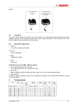
Page 11: ...e uncharged wire rope Drum brake Brake as slipping clutch for setting the brake moment for winches with disengaging clutch Special Parts For use in explosion dangerous areas are be installed some special units special treated surfaces or made in special material 5 Technical data Capacity FEM group wir erope Ø nec minimum breaking load useable wirerope length number of rope layers wire rope path pe...

Page 12: ...lation position 6 1 Installation of the winch The winches can be installed in any position desired make sure however that the prescribed rope exit is correct Make sure the attachment surface is flat plain and that installation is made stress free to ensure safe functioning Use the screws mentioned in the table for installation Tighten all screws evenly Distance of holes Capacity 1st layer holes of...

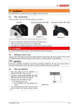
Page 13: ...ke is not working 6 4 Winding up of wire rope The wire rope must always be winded up tensioned When the last wire rope layer is winded onto the drum the flanged wheel must exceed the top layer by at least 1 1 2 times of the wire rope diameter NOTICE According to validated regulations and accident prevention regulations the wire rope length must be chosen so that at least 2 rope layers remain on th...

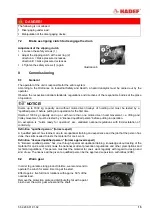
Page 14: ... the crank can removed in each position or the crank grip can fold back Lowering load turn anti clockwise Wirerope winch from 2000 kg capacity and up By changing the crank to the other driving point it is easier to move larger loads 7 1 Free wheeling mechanism of the drum For engaging or disengaging of the drum for controlled feeding out of the uncharged wirerope Disengaging Turn the drum approx 4...

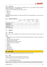
Page 15: ... trolley movement must be tested by a licensed qualified person before putting in operation An exception is hoists ready for operation acc validated national regulations with EU declaration of conformity Definition qualified person former expert A qualified person has learned due to occupational training and experience and the job that the person has done the skills needed to tests the material fo...

Page 16: ...pacity mentioned on the type plate Check the brake when lifting lowering it must hold the load safely Check the condition of the wire rope and the supporting structures Check screw connections 11 Maintenance 11 1 General All monitoring servicing and maintenance operations are to ensure correct functioning of the equipment they must be effected with utmost care Only qualified persons may do this wo...

Page 17: ...ces and load hook Check for fissures and deformation X 13 Service 13 1 Wire rope Wire ropes have to be exchanged by new original wire ropes if they show corrosion fracture or if they are worn Checks Fastening screws must be checked before commissioning and at least every 3 months tighten them if necessary Kind and number of broken threads Position of the broken threads Timing sequence of occurrenc...

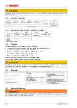
Page 18: ...aults are found in the following table For the repair of failures please contact our service department CAUTION Trouble caused by wear or damage to parts such as wire ropes chains chain wheels axes bearings brake parts etc must be remedied by replacing the parts with original spare parts 15 Remedy Trouble Cause Remedy It is difficult to turn the crank if unloaded not lubricated worm gear is dirty ...

Page 19: ...carried out in reverse order to the assembly Please make sure that all operating material is disposed of in accordance with environmental regulations 16 1 Temporary decommissioning Measures are as above Also read the chapter Transport and storage 16 2 Final decommissioning disposal Measures are as above After disassembly ensure that the disposal of the equipment and any materials it contains is ca...

Reviews: