background image


5.52.182.00.01.07 


19


13.2 

Pulleys 


13.3 

Load hook 

  Check bearings and pulleys yearly 
  Clean and lubricate the bearings of hooks and pulleys with grease 
  Slight bearings are maintenance free 
  When bearings resp. slight bearings are worn of, change the complete pulley 


13.4 

Gear 

Regular  checks  of  lubrication  are  necessary.  The  teeth  must  be  cleaned  and  re-lubricated  after  approx.  3 
years. We recommend to use a lubricant of class EP2 or similar products. In  case of severe conditions  of 
use (e.g. dust, regular lifting of the nominal load,etc.), please shorten maintenance intervals. 


13.5 

Trolley 

  Trolleys are lifetime lubricated, Refill lubricant is normally not necessary. 
  Lubricate gear rim and pinion drive each ¼ year or if required more often, with grease. 


13.6 

Gear spring pressure brake 

During  the  check,  brake  lining  wear  is  verified.  The  brake  linings  must  be  replaced  when  the  wear  limit  is 
already reached at one position of the lining, - as this can be the case when wear of the linings is irregular. 


CAUTION!


The brake linings must be free from fracture. Avoid oil, grease, dirt and humidity on the brake linings as this 
increases wear. 


13.7 

Overload protection 


DANGER!


The factory setting of the overload protection/slipping clutch is secured by sealing. In case of any changes 
will void the warranty. Should maintenance be necessary, please contact a service company authorized by 
the manufacturer. 


Use 


Recommendation 


Interval 

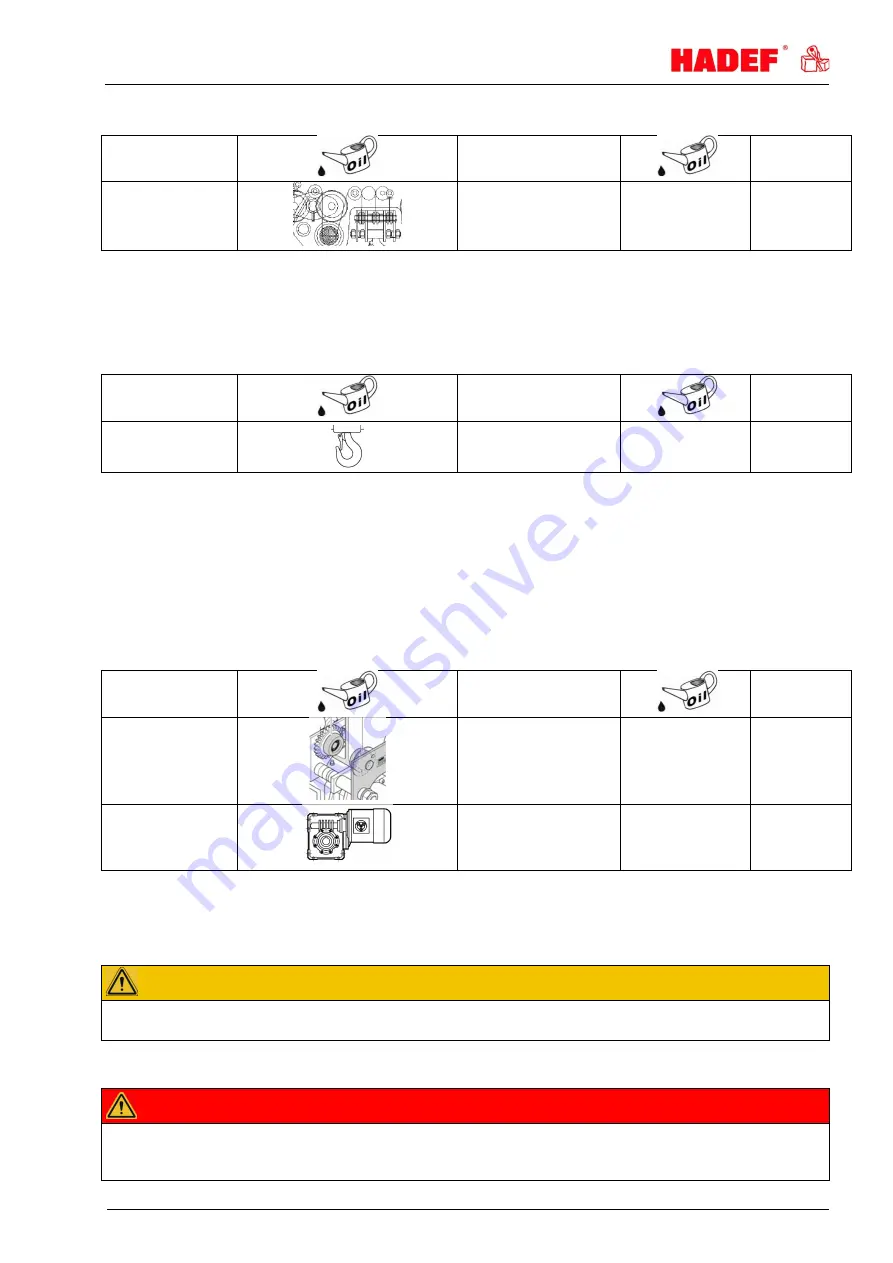
Pulleys 


FUCHS 
RENOLIN PG220 

Acc. to demand 

12  month 

Use 


Recommendation 


Interval 

Load hook  
bearing 


FUCHS 
RENOLIN PG220 

Acc. to demand 

12  month 

Use 


Recommendation 


Interval 

Pulleys 
Gear rim 
Drive pinion 


FUCHS 
RENOLIT FEP2 

0,1 kg 

3  month 

Travelling gear 
If available 


SHELL 
Tivela S320 

--- 

Life time 

lubrication 

Summary of Contents for 29/12 HH

Page 1: ...5 52 182 00 01 07 Rev 07 HADEF Spur Gear Chain Hoist Type 29 12 Ultra low headroom configuration with monorail hand geared trolley HH Installation Operating and Maintenance Instructions ...

Page 2: ...1 Information 3 2 Safety 4 2 1 Warning notice and symbols 4 2 2 Duty of care of the owner 4 2 3 Requirements for the operating personnel 5 2 4 Appropriate use 5 2 5 Basic safety measures 6 3 Transport and Storage 7 3 1 Transport 7 3 2 Safety device for transport 7 3 3 Storage 7 4 Description 7 4 1 Areas of application 7 4 2 Design 7 4 3 Functions 8 4 4 Important components 8 5 Technical data 9 6 I...

Page 3: ...tified quality assurance system as per ISO 9001 The production of components at our work is subject to strict intermediate checks After assembly each product is subject to a final test with overload For the operation of hoists the national accident prevention regulations apply in Germany amongst others The stated performance of the devices and meeting any warranty claims require adherence to all i...

Page 4: ...or they must be suitable for use in area prone to explosion The owner is responsible for this However in everyday operation this degree of safety can only be achieved if all measures required are taken It falls within the duty of care of the owner user of the devices to plan these measures and to check that they are being complied with Complete the operating and installation instructions by any in...

Page 5: ...st be used Non compliance will result in any warranty claims becoming void Liability and warranty will become void if unauthorized modifications of the units are made by the user The permissible ambient temperature when operating the devices Type of drive Device classification for Not explosive atmosphere Explosive atmosphere according to ATEX Manually driven 20 C 50 C 20 C 40 C Motor driven 20 C ...

Page 6: ...n to the regulations for load carrying devices UVV for both positive and non positive methods of attaching loads The lifting tackle or the load must be securely attached to the hook and be seated at the bottom of the hook The safety catch of hooks must be closed When charged the housing may not be in contact somewhere Stop lowering the load when the bottom block or the load is being set down or is...

Page 7: ... chains and brakes against corrosion 4 Description 4 1 Areas of application The devices must be as far as possible installed in a covered room If they are used in the open protect the units against the effects of weather such as rain hail snow direct sunshine dust etc we recommend to use a cover in parking position If the device is set up in a continuously humid environment with strong temperature...

Page 8: ...ist A load pressure brake prevents automatic lowering of the load after releasing the hand chain In combination with hand geared trolleys the trolley is moved to the left or to the right side by pulling the hand chain In combination with push travel trolleys the trolley is moved by pushing or pulling the load or without load by pulling the load chain NOTICE The best protection against functional f...

Page 9: ...ox kg 75 145 235 380 380 Table 2 Capacity kg 10000 12000 16000 20000 25000 30000 Number of chain falls 2 2 4 4 4 6 Load chain mm 16x45 16x45 16x45 16x45 16x45 16x45 Load bar size at beam flange width from to mm 185 310 185 310 185 310 185 310 185 310 185 310 Lifting path when reeling off 30 m of hand chain mm 35 35 17 5 17 5 17 5 11 7 Hand chain pull for lifting N 190 230 160 190 240 190 Travel pa...

Page 10: ...ustment must be repeated if necessary 1 side plates 2 load bars 3 hexagon nut 4 safety nuts 5 distance tubes 6 washers 7 8 rubber disc depended on type 9 suspension eye CAUTION The distance X between the wheel flanges of the trolley wheels must be for trolleys up to 3 2 t 2 3 mm 1 1 5 mm each side bigger and for trolleys from 4 t up 3 5 mm 1 5 2 5 mm each side bigger than the flange width B of the...

Page 11: ...readed rod 9 Tighten nut 10 first then nut 11 The trolleys are moved by four wheels The axis of the driven wheel is set slightly lower to ensure the required wheel pressure for traversing when the device is not under load To prevent the slack between load bolt 2 and the corresponding bores which is due to the manufacturing process having a negative impact on wheel pressure proceed as follows Place...

Page 12: ...ube bearing and secure them again after the side plates have been pushed together Illustration 8 1 set collar 2 load bar 3 safety screw 4 hexagon nut 5 washer NOTICE For reaching the ultralow headroom the deflection of chain caused a rotator symmetrical displacement of chain pulleys This will be shown when lifting and lowering by rocking actions of the bottom block This is made by system and const...

Page 13: ...ockwise Illustration9 NOTICE For double lifting mechanism Operate both lifting mechanism synchronous resp evenly CAUTION Run in of chain into the chain container for hoist with double lifting mechanism For a correct run in of chain into both chain containers the lowering operation must be carried out without load at certain intervals until both chain container are empty For motorized devices with ...

Page 14: ...tion qualified person former expert A qualified person has learned due to occupational training and experience and the job that the person has done the skills needed to tests the material for one s work Definition licensed qualified person former approved expert A licensed qualified person has due through special occupational training knowledge about testing of the material for one s work and know...

Page 15: ...1 2 Monitoring The monitoring and servicing intervals stated are valid for operation under normal conditions and single shift operation In case of severe operating conditions e g frequent operation with full load or special environmental conditions e g heat dust etc the intervals must be shortened correspondingly 11 3 Replacing the load chain CAUTION If there is any visible damage and when the con...

Page 16: ...isc thickness X Check sprocket wheels ratchet wheels pawls bolts X Clean and lubricate the load chain X X X Check the load chain for elongation and wear X Check the load hook for cracks and deformation X Load hook check the safety latch X X Check and lubricate the bearing of the chain pulleys X X Check the chain pulleys X X Check the rubber end stops X X X Check the trolley wheels for wear X Check...

Page 17: ...le are reached due to wear or deformation the chain must be replaced 12 3 Checking the load hook Load hook X measuring distance hook mouth width Y measured length from hook no 6 H thickness of hook saddle Illustration 13 Dimension mm Capacity in t chain falls 1 2 2 2 3 2 2 5 4 6 3 4 10 2 12 2 16 4 20 4 25 4 30 6 X or Y 32 38 45 50 50 50 50 130 145 145 180 H 29 37 48 58 58 58 58 85 95 95 106 Please...

Page 18: ... the formation of a lubricating film within the links The adjacent link points must always be lubricated to prevent excessive wear If the same lifting operations are carried out constantly the switching area from a lifting to a lowering movement must be given special attention Thoroughly effected lubrication of the chain will prolong the life of the chain by approx 20 times compared to dry run wit...

Page 19: ...ring pressure brake During the check brake lining wear is verified The brake linings must be replaced when the wear limit is already reached at one position of the lining as this can be the case when wear of the linings is irregular CAUTION The brake linings must be free from fracture Avoid oil grease dirt and humidity on the brake linings as this increases wear 13 7 Overload protection DANGER The...

Page 20: ...e brake linings Load chain is twisted Align the load chain Defect of chain gear or chain wheels Do maintenance and replace defective parts by original spare parts Pawl does not engage properly Check the pawl and replace it if necessary Pawl spring is missing Do maintenance and replace defective parts by original spare parts It is difficult to lift the load Overload reduce the load to nominal load ...

Page 21: ...decommissioning leaving plenty of space Read the chapter Safety instructions Disassembly is carried out in reverse order to the assembly Please make sure that all operating material is disposed of in accordance with environmental regulations 16 1 Temporary decommissioning Measures are as above Also read the chapter Transport and storage 16 2 Final decommissioning disposal Measures are as above Aft...

Reviews: