


English - 3
Assembly instructions
BASE ASSEMBLE (Pictures 1 to 6)
1.
Carefully turn the fan over, placing it on a smooth surface.
2.
Loosen the base locking nut from the bottom of the unit by turning it anticlockwise.
Put it down the length of the power cord as the (Picture 1).
3.
Run the power cord through the central gap between the two halves of the
unassembled base (Picture 2).
4.
Connect two halves by pushing the plastic pegs on each half into the corresponding
slots on the other half as the (Pictures 3-5).
5.
Fasten the locking nut clockwise between the round base and the fan body as the
(Picture 6).
IMPORTANT:
Make sure that the power cord passes through the guides on the rear
half of the base.
Putting into Service
Working place
Choose a suitable location and a non-slip, flat surface.
Never place the device directly next to heaters or other heat sources. There is always the
danger of fire!
Electrical Connection
1.
Connect the device to a duly installed 220-240V~50/60Hz protective contact socket.
2.
Before inserting the plug into the socket, make sure that the mains voltage to be used
matches that of the device. You can find this information on the nameplate.
How to use
Warning:
Make sure that the base is properly assembled before switching on.
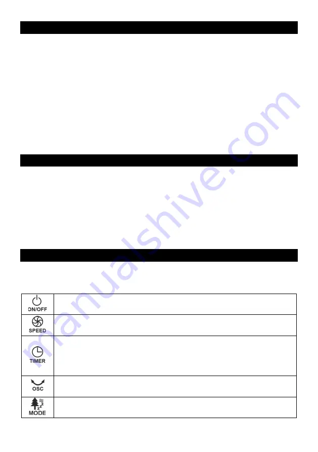
DESCRIPTION OF THE CONTROL PANEL
Power ON/OFF
–
Press this button to turn on the fan. The display will be lit
and shows the current room temperature. Press again to turn off the fan.
Serves to set the fan speed. Repeatedly press the button to toggle the
speed from low to high.
This button serves to set the timer. The timer can be set in the range from 1
hour to 12 hours. Repeatedly press the button to set the time for which the
fan will run. The timer duration is shown on the display. After the set time
has elapsed, the fan will turn off automatically.
Serves to turn the oscillation on / off. Press the button to turn oscillation
on. Press again to turn it off.
Serves to select the operation mode. Repeatedly press the button to select
the required operation mode:
Summary of Contents for Elite Tower TF-R36.005A
Page 2: ...Fig 1 Fig 2...
Page 31: ...29 H GER H GER...
Page 32: ...30 8 8 8 1 2 3 4 5...
Page 33: ...31 1 6 1 2 1 3 2 4 3 5 5 6 1 220 240V 50 60Hz 2 Power ON OFF 1 12...
Page 34: ...32 NORMAL NATURAL SLEEP CR2025 1 2...
Page 36: ...34 1 2 3 4 5 6 7 8 9...
Page 37: ...35 10 11 12 13 14 15 16 17 2019 771 2019 770...
Page 38: ......
Page 39: ......


