Chapter 6, Troubleshooting
6-33
Warning!
It is imperative that the operator record the codes listed if safety
system fault detection occurs. This information will be needed to
identify the reason for the safety system fault detection. It is also
imperative that the codes are properly labeled as COMMAND,
CHANNEL 1 FAULT, CHANNEL 2 FAULT, CHANNEL 1
CRITICAL, and CHANNEL 2 CRITICAL.
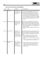
The command register defines the mode of operation the machine was in
when the fault occurred by displaying one of these hexadecimal codes.
Table 6-1, Error Codes of the Command Register
Code
Critical Fault
Description
000000
Start Test Phase
Conducting system start-up tests.
000700
Stop
PCS2 is in Ready mode or STOP or the
PUMP START/STOP key has been
pressed.
001C00
Start Application
PCS2 is transitioning from the system
Phase
start-up to the application mode.
000B00
Draw
The CPU executes a Draw command.
001500
Return
The CPU executes a Return command.
000D00
Pause
The PCS2 is transitioning from state to
state.
001A00
Auto Prime
The CPU executes a Prime command.
The fault register defines the actual fault that was detected. Each fault has
a hexadecimal code associated with it. If only one fault occurs, then one
of the codes listed in the following table will be displayed. If two or more
faults occur simultaneously, the actual code displayed is the sum of the
two or more codes.
!
Command
Register
Fault Register


