Chapter 2, Machine Part Replacement Reference
2-21
Power Supply
Assembly
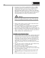
1. Remove the rear panel. (See page 2-2.)
2. Using a 1/4" wrench (or equivalent), remove (2) #4-40 nuts on either
side of the power input module.
3. Disconnect the left top (blue) and bottom (brown) AC power lines
from the power input module and disconnect the ground lug from the
ground bus on the cabinet.
Fuse
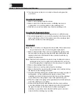
1. Pry above the power switch on the power entry module to open the
fuse cover.
2. Pry out each fuse holder.
3. Replace with same size and rating fuse (5a 250V).
Fuse Holder Reassembly Notes
When replacing fuse holders, be sure arrows on fuse holder and power
input module face the same direction.
Replace Todd Power Supply with Todd Power Supply
Note:
Use the following directions if replacing a Todd power supply (P/N
18878-00) with another Todd power supply.
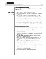
1. Remove the front and rear panels. (See page 2-2.)
2. Disconnect P1, P2, and P3 from the centrifuge controller card.
3. Disconnect P405 from the centrifuge distribution card and thread the
cable through the cabinet to the photoelectric assembly.
4. Disconnect P507 from the backplane card.
5. Remove the (4) Phillips head screws securing the power supply cage
access panel, and remove the panel (located at the rear of the cabinet).
6. Using a 11/32" wrench, remove the (2) #8-32 hex nuts securing the
line conditioner to the cabinet, and pull the line conditioner away
from the cabinet.
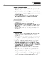
7. Unplug the L (brown, located on the left) and N (blue, located on the
right) AC power lines from the power supply.
8. Using a 5/16" wrench, disconnect the (1) #6-32 nut and ground from
the power supply fan.
9. Remove the (2) optic cables from the photoelectric assembly by
unscrewing the (2) plastic thumb screw fasteners.
10. Remove the (2) Phillips head screws securing the power supply cage
to the cabinet.
11. Pull the power supply cage out the rear cabinet cavity by lifting the
rear edge and pulling the front edge away from the plastic edge clips
on the cabinet base.
Power Entry
Module


