

ESEN-RMAR Installation, Commissioning & Operating Manual
Approved Document Ref: UI-ESEN-RMAR-01 Issue 5.0
9
INSTALLATION
ESD PRECAUTION
GENERAL
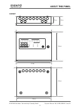
MOUNTING THE CABINET
Electronic components are vulnerable to damage by Electrostatic Discharges (ESD). An ESD wrist strap,
suitably grounded, should be worn at all times when handling pcbs. These wrist straps are designed to
prevent the build up of static charges, not only within a persons body, but on many other materials.
ESD damage is not always evident immediately, faults can manifest themselves at anytime in the future.
All pcbs should be stored in static shielded bags (silvered) for safe keeping, when not mounted in the
control panel.
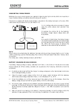
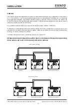
Care should be taken with regards to avoiding the close proximity of high voltage cables or areas likely
to induce electrical interference. Earth links should be maintained on all system cables and grounded in
the control panel. The detection and sounder circuit cabling is classed as extra low voltage and must be
segregated away from mains voltage.
•
Any junction boxes used should be clearly labelled FIRE ALARM.
•
Any ancillary devices, e.g. door retaining magnets, must be powered from a separate power source.
•
Any coils or solenoids used in the system must be suppressed, to avoid damage to the control
equipment.
The panel is only suitable for mounting in dry control rooms or dry accomodation spaces. The site chosen
for the location of the panel should be clean, dry and not subject to shock or vibration. Damp, salt air or
environments where water ingress or extremes of temperature may affect the panel must be avoided. The
temperature should be in the range -5° to +40°C, and the relative humidity should not exceed 95%.
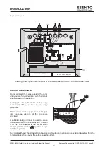
Before mounting the cabinet remove the main PCB.
Remove the power supply module connecting wires from the main PCB, taking care to note where to re-
connect them. The main PCB can then be carefully pulled off it’s mounting clips.
Secure the cabinet to the wall using the four indented holes in the back box. Ensure the box is mounted
level and in a convenient location where it may be easily operated and serviced.
External cables should be glanded via preformed knockouts at the top and rear of the cabinet. Remove
any knockouts and ensure the cabinet is clear of swarf etc prior to refitting the PCB. Always ensure that if
a knockout is removed, the hole is filled with a good quality cable gland. Any unused knockouts must be
securely blanked off.
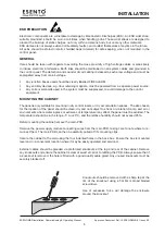
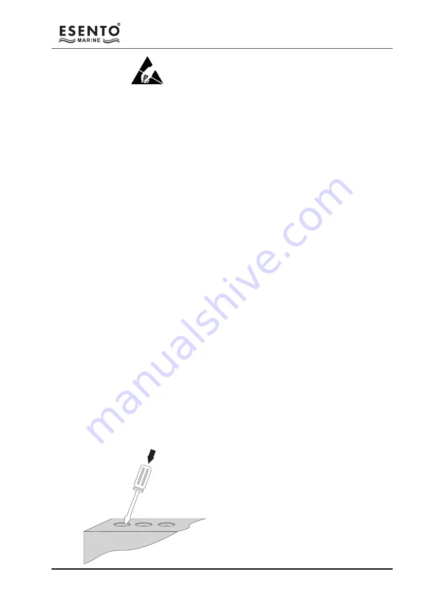
Knockouts should be removed with a sharp tap at the
rim of the knockout using a flat 6mm broad bladed
screwdriver.
Use of excessive force will damage the enclosure
around the knockout.
Summary of Contents for ESENTO MARINE ESEN-R-12MAR
Page 24: ...www haes tech com ...


