


ESEN-RMAR Installation, Commissioning & Operating Manual
Approved Document Ref: UI-ESEN-RMAR-01 Issue 5.0
13
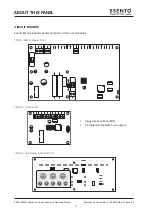
INSTALLATION
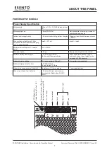
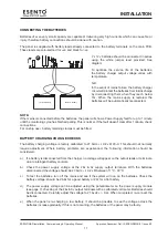
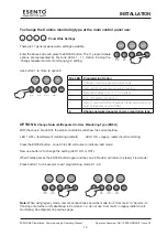
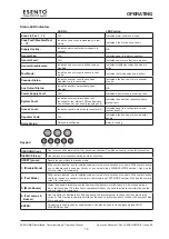
With the zone 6 fire LED lit, the amber, fault LEDs will show the current setting.
LED 1 OFF = fault tolerant monitoring (default). LED 1 ON = legacy, radial circuit monitoring.
Press the ENTER button, zone 6 fire LED will pulse to indicate ‘edit mode’.
Now use button 2 to change the setting (LED 1 ON or OFF).
When finished press the ENTER button again and the zone 6 fire LED will return to steady ‘view mode’.
Press button 1 for 3 seconds to exit programming mode 2-1-2-3.
RESOUND
SILENCE
RESET
ENTER
1
2
3
4
Disable
Mode
Test
Mode
Mute
Buzzer
Test
Lamps
RESOUND
SILENCE
RESET
ENTER
1
2
3
4
Disable
Mode
Test
Mode
Mute
Buzzer
Test
Lamps
2
1
2
3
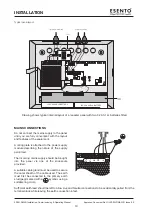
Panel Wide Settings
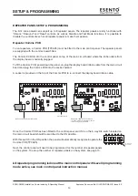
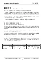
There are 11 general, panel wide, settings available.
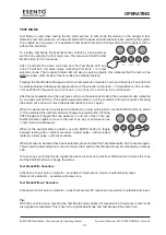
Enter the above code and press the ENTER button. The 11 programmable
options are represented by fire zone LEDs 1 - 11, Option 6 being the,
‘change repeater comms monitoring type’ setting.
Use button 1 to move to option 6
RESOUND
SILENCE
RESET
ENTER
1
2
3
4
Disable
Mode
Test
Mode
Mute
Buzzer
Test
Lamps
RESOUND
SILENCE
RESET
ENTER
1
2
3
4
Disable
Mode
Test
Mode
Mute
Buzzer
Test
Lamps
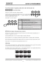
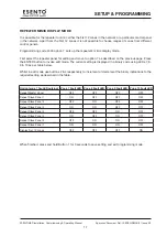
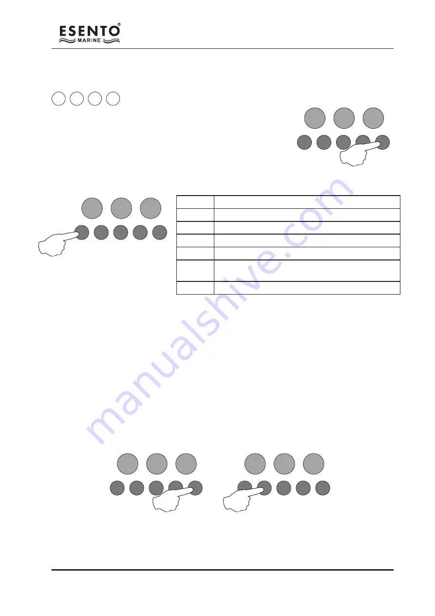
Fire LED Programming Option
1
Change / remove keypad access code
2
Set number of repeater panels on system
3
Set output delay time (1 - 10 minutes)
4
Turn off battery monitoring
5
Set up internal PCB configuration (add extension zone
card or repeater comms PCB)
6
Change network/repeater comms monitoring type
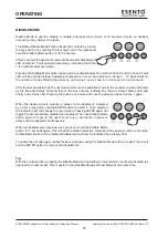
OPTION 6.
Change Network/Repeater Comms Monitoring Type (EN54!)
To change the Comms monitoring type at the main control panel use:
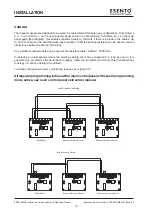
Note:
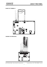
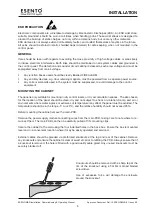
When using legacy mode, comms connections should be made from ‘Comms-A’ to ‘Comms-A’.
If linking onto further units double up in Comms-A. I.e. do not use ‘Comms-B’ in legacy radial circuit
monitoring. See diagram on previous page.
Summary of Contents for ESENTO MARINE ESEN-R-12MAR
Page 24: ...www haes tech com ...


