ESEN-RMAR Installation, Commissioning & Operating Manual
Approved Document Ref: UI-ESEN-RMAR-01 Issue 5.0
14
SETUP & PROGRAMMING
REPEATER PANEL SETUP & PROGRAMMING
The 8-12 zone panels can support up to 8 repeater panels. The repeater panels are fully functional with
‘Silence’ ‘Resound’ and ‘Reset’ controls, as well as Disable and Test Mode functions. It is possible to
disable the controls of each or all repeater panels to make them passive.
Repeater Comms PCB
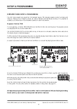
To run repeaters, a Comms PCB (TPCA05) must be fitted to the main control panel. The repeater panels
are supplied with the comms board fitted.
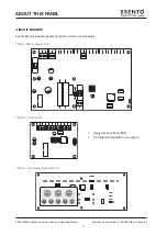
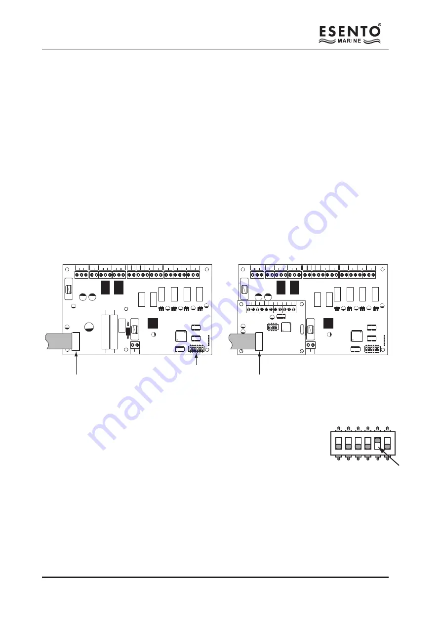
The Comms PCB fits into the control panel on top of the main circuit board where the ribbon cable from
the display board is normally plugged.
To fit the Comms PCB, power down the panel, un-plug the display board ribbon cable from the main circuit
board and plug the Comms PCB into the socket instead.
A socket is provided on the top of the Comms PCB to re-connect the display board ribbon cable.
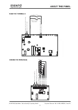
Once the Comms PCB has been fitted to the control panel, switch 5 on the 6 way DIL switch located on
the main circuit board should be switched to the ON position.
With this switch in the ON position the panel will automatically recognise & operate the
Comms PCB (TPCA05).
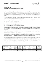
Next, the control panel will need to be programmed for the number of repeater panels
on the system. To set up the number of repeater panels on the system, see page 15.
All repeater programming is done at the main control panel with Level 3 programming
mode active, see main control panel instruction manual.
PSU
@ +
+
-
-
+ -
+ -
+ -
+ - + - + - + -
28V 0V
C NC NO C NC NO
FIRE
FAULT
FR
FLT
CC
PUL
-OP -OP -IP -IP
SNDR1 SNDR2
ZONE1 ZONE2 ZONE3 ZONE4
BATTERY
PSU
@ +
+
-
-
+ -
+ -
+ -
+ - + - + - + -
28V 0V
C NC NO C NC NO
FIRE
FAULT
FR
FLT
CC
PUL
-OP -OP -IP -IP
SNDR1 SNDR2
ZONE1 ZONE2 ZONE3 ZONE4
BATTERY
COMS A COMS B 28
V+
SW -ve OUTPUTS
+ - + -
1
2
3
4
5
6
1
2
3
4
ON
ADDRESS
Disconnect display board ribbon cable
6 way DIL switch
Plug Comms PCB into the socket and
re-connect dispay board ribbon cable to
socket on top of Comms PCB
1
2
3
4
5
6
ON
1
2
3
4
5
6
ON
ON = Network/
Repeater mode
1
2
3
4
5
6
ON
Summary of Contents for ESENTO MARINE ESEN-R-12MAR
Page 24: ...www haes tech com ...

