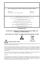
background image

IMPORTANT NOTE

PLEASE READ THIS MANUAL BEFORE HANDLING THE EQUIPMENT AND 

OBSERVE ALL ADVICE GIVEN IN IT

THIS PARTICULARLY APPLIES TO THE PRECAUTIONS NECESSARY TO AVOID 

E.S.D

The panel is safe to operate provided it has been installed in compliance with the manufacturer’s instructions 
and used in accordance with this manual.

Hazardous voltages are present inside the panel—DO NOT open it unless you are qualified and authorised 

to do so. There is no need to open the panel’s enclosure except to carry out commissioning, maintenance 
and remedial work. This work must only be carried out by competent service personnel who are fully 
conversant with the contents of the panel’s installation manual and have the necessary skills for maintaining 
this equipment.

This fire alarm system requires periodic checks as specified in BS 5839 Part 1 It is the responsibility of the 

system user to ensure it is regularly serviced and maintained in good working order.

Disclaimer

No  responsibility  can  be  accepted  by  the  manufacturer  or  distributors  of  this  fire  alarm  panel  for  any 

misinterpretation of an instruction or guidance note or for the compliance of the system as a whole. The 
manufacturer’s policy is one of continuous improvement and we reserve the right to make changes to 

product specifications at our discretion and without prior notice. E & O E.

IMPORTANT SAFETY NOTES

Haes Technologies Ltd, Unit 3, Horton Industrial Park, West Drayton, UB7 8JD

Model Number

MED Ref No.

Esento Marine 12 way repeater panel ESEN-R-12MAR

0832-MED-1086

ATTENTION

European Standard EN54-2 : 1997 + A1 : 2006

Control and indicating equipment for fire detection and fire alarm systems for buildings.

Provided Options (with requirements):

Output to fire alarm devices, dependency type ‘A’, test condition

European Standard EN54-4 : 1997 + A1 : 2002 + A2 : 2006

Power supply equipment for fire detection and fire alarm systems for buildings.

European Standard BS IEC60092-504 : 2001

Electrical installations in ships, special features, control and instrumentation.

European Standard BS IEC60533 : 1999

Electrical and electronic installations in ships, electromagnetic compatibility.

Summary of Contents for ESENTO MARINE ESEN-R-12MAR

Page 1: ...Installation Commissioning Operating Manual 12 WAY FULLY FUNCTIONAL PASSIVE REPEATER PANEL Approved Document UI ESEN RMAR 01 Issue 5 0 REPEATER PANEL MED Ref 0832 15 ...

Page 2: ...imer No responsibility can be accepted by the manufacturer or distributors of this fire alarm panel for any misinterpretation of an instruction or guidance note or for the compliance of the system as a whole The manufacturer s policy is one of continuous improvement and we reserve the right to make changes to product specifications at our discretion and without prior notice E O E IMPORTANT SAFETY ...

Page 3: ...IFICATION 6 POWER SUPPLY MODULE 7 INSTALLATION 8 SAFETY 8 ESD PRECAUTIONS 9 GENERAL 9 MOUNTING THE CABINET 9 MAINS CONNECTIONS 10 CONNECTING THE BATTERIES 11 CABLING 12 SETUP PROGRAMMING 14 INSTALL COMMS PCB IN MAIN CONTROL PANEL 14 SET NUMBER OF REPEATER PANELS ON MAIN CONTROL PANEL 15 REPEATER PANEL ADDRESSING 15 PROGRAMMING REPEATER PANELS 16 REPEATER MIMIC DSPLAY MODE 17 OPERATING 18 PANEL CON...

Page 4: ...t comms monitoring This then allows any topology of comms cabling to be utilised The main circuit board has 2 switch ve inputs which can be used to sound or pulse the alarms These inputs can also be re programmed for use as PSU fault inputs The internal comms PCB has 6 switch ve programmable outputs Different key types are used for the door lock and the activate controls key switch It is also poss...

Page 5: ...ESEN RMAR Installation Commissioning Operating Manual Approved Document Ref UI ESEN RMAR 01 Issue 5 0 3 ABOUT THIS PANEL CABINET 57mm 80mm 260mm 308mm 250mm 300mm ...

Page 6: ...omprise of three circuit boards PSU 28V 0V C NC NO C NC NO FIRE FAULT FR FLT CC PUL OP OP IP IP SNDR1 SNDR2 ZONE1 ZONE2 ZONE3 ZONE4 BATTERY COMS A COMS B 28 V SW ve OUTPUTS 1 2 3 4 5 6 1 2 3 4 ON ADDRESS 1 2 3 4 ENTER RESOUND SILENCE RESET TPCA01 RMAR Master PCB TPCA05 Comms PCB TPCA03 LED Display Controls PCB Piggy backs on Main PCB 6 programmable switch ve outputs ...

Page 7: ... ZONE4 BATTERY 28v input for power supply Temperature compensation voltage control link Alert pulses sounders Precint class change activates sounders Switched ve inputs Switched ve outputs Max load 40mA To 0 volts COMS A COMS B 28 V SW ve OUTPUTS 1 2 3 4 5 6 1 2 3 4 ON ADDRESS Comms output to next panel Comms input from previous panel 28v output fused 500mA Switch ve O P Switch ve O P Switch ve O ...

Page 8: ... Electrical Specification Inputs Outputs TPCA01 RMAR Main PCB Terminal capacity 0 5mm2 to 2 5mm2 solid or stranded wire PSU output Power supply voltage control line For temperature compensation control PSU Input 28vdc supply input Diode protected for reversal and independent short circuit Max current 3 amps Max input current 3 amps Input voltage 22vdc to 32vdc Inputs CC PUL Switched ve inputs conn...

Page 9: ...r panel I min 63mA Maximum ripple 1 0 V pp Supply and charger fault monitored Min max battery size and type 2 x 3 2Ahr 12volt VRLA Use Yuasa NP range batteries Other equivalent batteries may be used but have not been tested for the purposes of EN54 approval Battery charging voltage 27 3 vdc nominal at 20 deg C Temperature compensated Battery charging output current 1 5A PSU 630mA Current limited 1...

Page 10: ...take such steps as are necessary to ensure that any appropriate information about this product is made available by you to anyone concerned with its use This equipment is designed to be operated from 230V AC 50 60 Hz mains supplies and is of Class I construction As such it must be connected to a protective earthing conductor in the fixed wiring of the installation Failure to ensure that all conduc...

Page 11: ...sed in the system must be suppressed to avoid damage to the control equipment The panel is only suitable for mounting in dry control rooms or dry accomodation spaces The site chosen for the location of the panel should be clean dry and not subject to shock or vibration Damp salt air or environments where water ingress or extremes of temperature may affect the panel must be avoided The temperature ...

Page 12: ...e brought into the panel via one of the knockouts provided A suitable cable gland must be used to secure the outer sheath of the cable used The earth must first be connected to the primary earth stud peg marked with a symbol using a suitable ring crimp Sufficient earth lead should be left to allow Live and Neutral connections to be accidentally pulled from the terminal block while leaving the eart...

Page 13: ...ring cylce has finished polling This is normal If the fault doesn t clear after 1 minute check connections For on ship use battery retaining clamps must be fitted The battery charging voltage is factory calibrated to 27 3vdc 0 2v 20o C This should not normally require adjustment Where battery problems are experienced the following information should be considered a If a battery is disconnected fro...

Page 14: ...ed in a loop as shown it is possible to re programme the panel back to legacy radial circuit comms monitoring This then allows any topology of comms cabling to be utilised To change the repeater comms monitoring type see over page 13 AllrepeaterprogrammingisdoneatthemaincontrolpanelwithLevel3programming mode active see main control panel instruction manual COMS A COMS B 28 V SW ve OUTPUTS 1 2 3 4 ...

Page 15: ...the above code and press the ENTER button The 11 programmable options are represented by fire zone LEDs 1 11 Option 6 being the change repeater comms monitoring type setting Use button 1 to move to option 6 RESOUND SILENCE RESET ENTER 1 2 3 4 Disable Mode Test Mode Mute Buzzer Test Lamps RESOUND SILENCE RESET ENTER 1 2 3 4 Disable Mode Test Mode Mute Buzzer Test Lamps Fire LED Programming Option 1...

Page 16: ...the Comms PCB to re connect the display board ribbon cable Once the Comms PCB has been fitted to the control panel switch 5 on the 6 way DIL switch located on the main circuit board should be switched to the ON position With this switch in the ON position the panel will automatically recognise operate the Comms PCB TPCA05 Next the control panel will need to be programmed for the number of repeater...

Page 17: ...button 1 to move to option 2 RESOUND SILENCE RESET ENTER 1 2 3 4 Disable Mode Test Mode Mute Buzzer Test Lamps RESOUND SILENCE RESET ENTER 1 2 3 4 Disable Mode Test Mode Mute Buzzer Test Lamps Fire LED Programming Option 1 Change remove keypad access code 2 Set number of repeater panels on system 3 Set output delay time 1 10 minutes 4 Turn off battery monitoring 5 Set up internal PCB configuration...

Page 18: ...ive and to disable the battery monitoring on the repeater panel if no battery backup is required A further option is provided option 7 for use when used in a network it is possible for the repeater to mimic either the first 12 zones on a network or a particular control panel in the network Details of the repeater mimic display mode or shown over page Enter the above code and press ENTER The zone 1...

Page 19: ...tton to invoke edit mode The current setting is displayed in a binary code using LEDs 7 8 9 10 as per table below Whilst in edit mode use buttons 2 4 respectively to increment or decrement the binary indications to the required setting as descibed in the table When finished press and hold Button 1 for 3 seconds to save setting and exit programming mode Option zone 7 fire LED pulsing Zone 7 Fault L...

Page 20: ...de entry to activate the controls is enabled by default but can be disabled in the Level 3 engineering functions To activate the controls using the key switch Turn the key clockwise to the On position The Access Level indicator LED will light and all buttons on the keypad will now be operational To deactivate the controls turn the key back to the Off position and the Access Level indicator LED wil...

Page 21: ...rational without the need to activate controls Also has the numeric value 4 for code entry ENTER This button is used to confirm code entries It can also be used for fault diagnosis see FAULT DIAGNOSIS section LED On LED Pulsing Zones in Fire 1 12 N A Indicates alarm condition in zone Zone Fault Disabled Test 1 12 Indicates zone circuit is disabled or in test mode Indicates a fault in the zone circ...

Page 22: ...D and finally to the Delay LED Pressing the button once more will move the selection back to Zone 1 again When the desired circuit outputs or delays to be disabled is indicated by a slow pulsing LED use the ENTER button to select it Once selected the indicator LED will change to a rapid pulse Pressing ENTER again will toggle the circuit between disabled and enabled Then use Disable Mode button aga...

Page 23: ...ssing the button once more will move the selection back to Zone 1 again When the desired zone to be tested is indicated by a slow pulsing LED use the ENTER button to select it Once selected the indicator LED will change to a rapid pulse Pressing ENTER again will toggle the zone between in and out of test Then use Test Mode button again to move to the next zone Any or all zones can be in test mode ...

Page 24: ...www haes tech com ...

Reviews: