


ESEN-RMAR Installation, Commissioning & Operating Manual
Approved Document Ref: UI-ESEN-RMAR-01 Issue 5.0
21
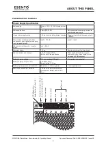
OPERATING
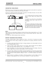
Test Mode is used when testing the fire alarm system. In test mode the devices in the zone(s) in test,
detectors and call points etc, can be activated and the panel will automatically reset, enabling the system
to be tested by one person. It is possible to test head removal monitoring and to test the system with or
without the sounders.
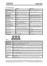
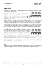
To initialise Test Mode, firstly activate the controls by turning the key
switch or by entering the four digit code. Then press and hold the Test
Mode button (2) for 3 seconds.
After 3 seconds the panel will bleep and the Test Mode LED and
Zone 1 Fault LED will pulse slowly, indicating that Zone 1 is in test
selection mode. The Sounder Status LED will also be pulsing rapidly, this indicates that the test will be
with
sounders. (Test mode without sounders is explained below)
Pressing the Test Mode button again will move test selection mode to Zone 2 and the Zone 2 Fault LED will
be pulsing instead. Subsequent presses will move the selection to Zones 3 - 12, dependant on the number
of zones fitted to the panel. I.e up to zone 4 on a 4 zone, 6 on a 6 zone, 8 on a 8 zone etc..
After the last available zone the next press will move the selection mode to the sounder circuits, indicated
by no Zone Fault LEDs on. This position selects whether or not the sounders will ring during test. Pressing
the button once more will move the selection back to Zone 1 again.
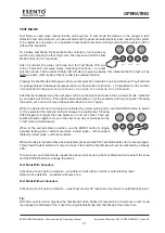
When the desired zone to be tested is indicated by a slow pulsing LED, use the ENTER button to select
it. Once selected the indicator LED will change to a rapid pulse. Pressing
ENTER again will toggle the zone between in and out of test. Then use
Test Mode button again to move to the next zone. Any or all zones can be
in test mode simultaneously.
When at the sounder status position, use the ENTER button to toggle
between testing with or without sounders. A rapid pulse = with sounders
(default), a slow pulse = without sounders.
When all zones to be tested have been selected, press and hold the Test Mode button for 3 seconds again.
This will exit the test selection mode. All zones in test and the Test Mode will now be indicated by a steady
LED.
To take zones out of test mode, repeat the above process using the Test Mode button to select the zone
and the ENTER button to change the status.
Test Mode With Sounders
Activation of a call point or detector - sounders will pulse twice, device is automatically reset.
Removal of a detector - sounders will pulse once.
Test Mode Without Sounders
Activation of a call point or detector - panel buzzer and LED response only, device is automatically reset.
Tip:
With the controls active, pressing the Test Mode button briefly will reveal which circuits are in test mode
(as opposed to disabled). This is useful if using Disable Mode and Test Mode at the same time.
TEST MODE
RESOUND
SILENCE
RESET
ENTER
1
2
3
4
Disable
Mode
Test
Mode
Mute
Buzzer
Test
Lamps
RESOUND
SILENCE
RESET
ENTER
1
2
3
4
Disable
Mode
Test
Mode
Mute
Buzzer
Test
Lamps
Summary of Contents for ESENTO MARINE ESEN-R-12MAR
Page 24: ...www haes tech com ...


