19
OPERATION MANUAL
4.5 INSTALLING & REMOVING THE TOOLING
The machine is fitted with a 3MT spindle to hold the tooling. While the taper will hold drills
where pressure is applied to the end of the drill, with milling cutters pressure is applied to the
side of the cutter , therefore the cutter arbour needs to be held also with a drawbar.
F
ig
.4.11
To install the tooling:
1. DISCONNECT THE MACHINE FROM POWER!
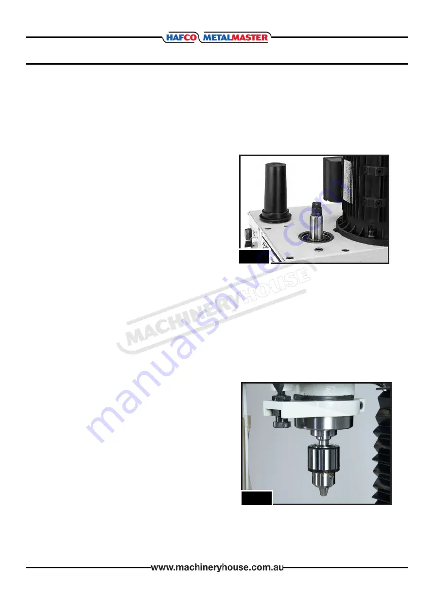
2. Remove the drawbar cap, so the drawbar is
exposed. (Fig.4.11)
3. Clean the mating surfaces then insert the tooling
in the spindle with force so that the taper holds
the arbour..
4. Working from the top, thread the drawbar by
hand into the tooling until it is snug, then use a
spanner to tighten it.
5. Replace the drawbar cap
To remove the tooling:
1. DISCONNECT THE MACHINE FROM POWER!
2. Remove the drawbar cap.
3. Un-thread the drawbar from tooling one full
rotation.
NOTE:
Do not fully un-thread the tooling from the
drawbar, or the drawbar and tool threads could be
damaged in the next step.
4. Tap the top of drawbar with hammer to unseat
the taper.
5. Hold onto the tooling with one hand and fully
un-thread the drawbar.
NOTE:
Height of drawbar inside spindle can be changed by rotating adjustment nut. Do not
overtighten the drawbar. Overtightening makes the tool removal difficult and may cause
damage to the arbor and threads.
F
ig
.4.12
07/11/2019
Instructions Manual for HM-46B (M138D)
19
Summary of Contents for HM-46B
Page 26: ...26 OPERATION MANUAL HEAD PARTS DIAGRAM 07 11 2019 Instructions Manual for HM 46B M138D 26 ...
Page 29: ...29 OPERATION MANUAL COLUMN AND TABLE PARTS 07 11 2019 Instructions Manual for HM 46B M138D 29 ...
Page 31: ...31 OPERATION MANUAL WIRING DIAGRAM 07 11 2019 Instructions Manual for HM 46B M138D 31 ...


