21
OPERATION MANUAL
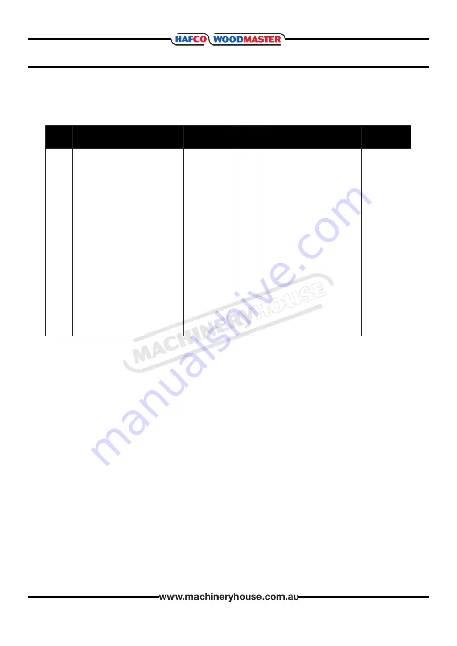
SPARE PARTS LIST DIAGRAM B
Key
No.
Description
Part No.
Key
No.
Description
Part No.
1b
2b
3b
4b
5b
6b
7b
8b
9b
10b
11b
12b
13b
14b
15b
16b
17b
18b
19b
Motor base
Spindle bushing & plastic insert
Guide column
Worm wheel frame
Worm wheel spindle
Bearing gland
Crank axle
Crank
Worm wheel
Connection rod
Bearing 6001-2RS
Worm gear
Cover, worm wheel frame
Plastic housing for worm gear
Motor
Bearing cover
Key 4x4x12
Hex set screw with flat M6x6
Hex bolt M8x75
P50-300-1B
P50-300-2B
P50-300-3B
P50-300-4B
P50-300-5B
P50-300-6B
P50-300-7B
P50-300-8B
P50-300-9B
P50-300-10B
P50-300-11B
P50-300-12B
P50-300-13B
P50-300-14B
P50-300-15B
P50-300-16B
P50-300-17B
P50-300-18B
P50-300-19B
20b
21b
22b
23b
24b
25b
26b
27b
28b
29b
30b
31b
32b
33b
34b
35b
36b
37b
Hex thin nut
M8
Key 5x5x50
E-clip 6mm
Connecting rod axle
Countersunk screw M4x6
Pan head screw M5x8
Hex bolt M8x20
Hex bolt M6x16
Washer 8
Spring washer 8
Self-locking nut M5
E-clip 4mm
Bearing 61804
Bearing 6006
Inner circlip
55mm
External circlip 30mm
Socket head screw M5x6
Pan head screw M4x12
P50-300-20B
P50-300-21B
P50-300-22B
P50-300-23B
P50-300-24B
P50-300-25B
P50-300-26B
P50-300-27B
P50-300-28B
P50-300-29B
P50-300-30B
P50-300-31B
P50-300-32B
P50-300-33B
P50-300-34B
P50-300-35B
P50-300-36B
P50-300-37B
Page 21
Instruction Manual for OS-140 (W792)
20/02/2019


