11
Fig. 9
Fig. 9
4.7 SETTING THE CUTTING TOOL WITH SPINDLE CENTERLINE
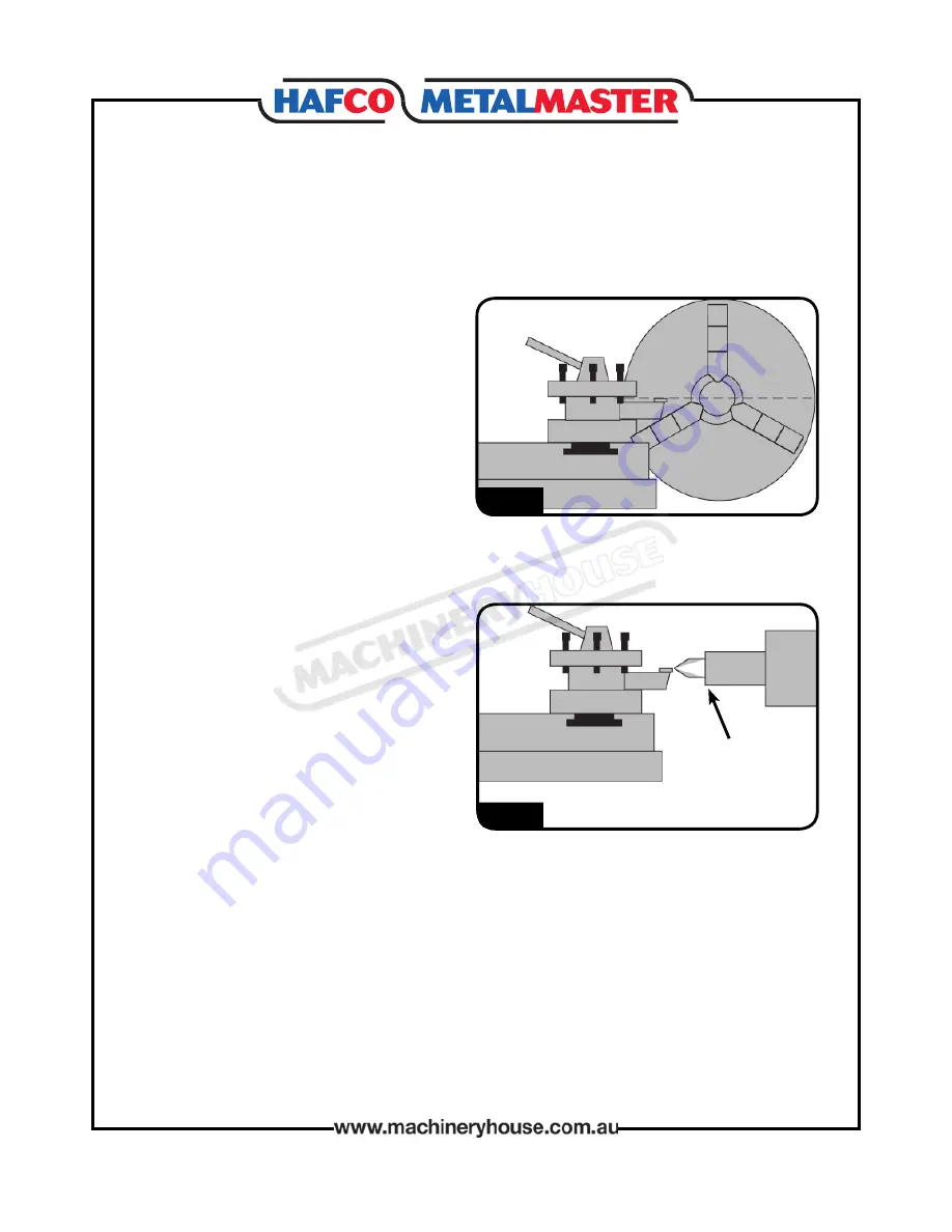
The tip of the cutting tool should be set up so that it is in line with the centre line of the spindle,
as illustrated in Fig. 8.
The cutting tool can be raised by placing steel
shims underneath it. The shims should be
as long and as wide as the cutting tool to
properly support it.
There are a number of ways to check that the
cutting tool is on the centre line of the spin-
dle.
Below are two common methods:
• Move the tailstock centre over the cross slide
and use a fine ruler to measure the distance
from the surface of the cross slide to the tip
of the centre. Adjust the cutting tool height so
it is the same distance above the cross slide
as the tailstock centre.
• Align the tip of the cutting tool with a tail-
stock centre, as described in the following
procedure.
1. Mount the cutting tool and secure the post
so the tool faces the tailstock.
2. Install a centre in the tailstock, and position
the tip near the cutting tool.
3. Lock the tailstock and quill in place.
4. Adjust the height of the cutting tool tip to
meet the centre tip, as shown. (Fig.9)
Tailstock Centre
Fig. 8
Fig. 8
Page 11
Instructions Manual for AL-320G (L141)
07/02/2018
Summary of Contents for AL-320G
Page 10: ...10 Thread Chart Page 10 Instructions Manual for AL 320G L141 07 02 2018 ...
Page 20: ...20 AL 320 BED PARTS Page 20 Instructions Manual for AL 320G L141 07 02 2018 ...
Page 23: ...23 AL 320 HEADSTOCK PARTS Page 23 Instructions Manual for AL 320G L141 07 02 2018 ...
Page 27: ...27 AL 320 BACK GEARS PARTS Page 27 Instructions Manual for AL 320G L141 07 02 2018 ...
Page 30: ...30 AL 320 GEARBOX PARTS Page 30 Instructions Manual for AL 320G L141 07 02 2018 ...
Page 33: ...33 AL 320 APRON PARTS Page 33 Instructions Manual for AL 320G L141 07 02 2018 ...
Page 36: ...36 AL 320 COMPOUND SLIDE PARTS Page 36 Instructions Manual for AL 320G L141 07 02 2018 ...
Page 38: ...38 AL 320 TAILSTOCK PARTS Page 38 Instructions Manual for AL 320G L141 07 02 2018 ...


