background image

22

OPERATION MANUAL

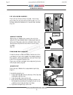
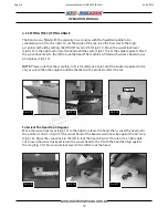
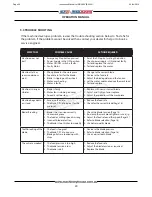
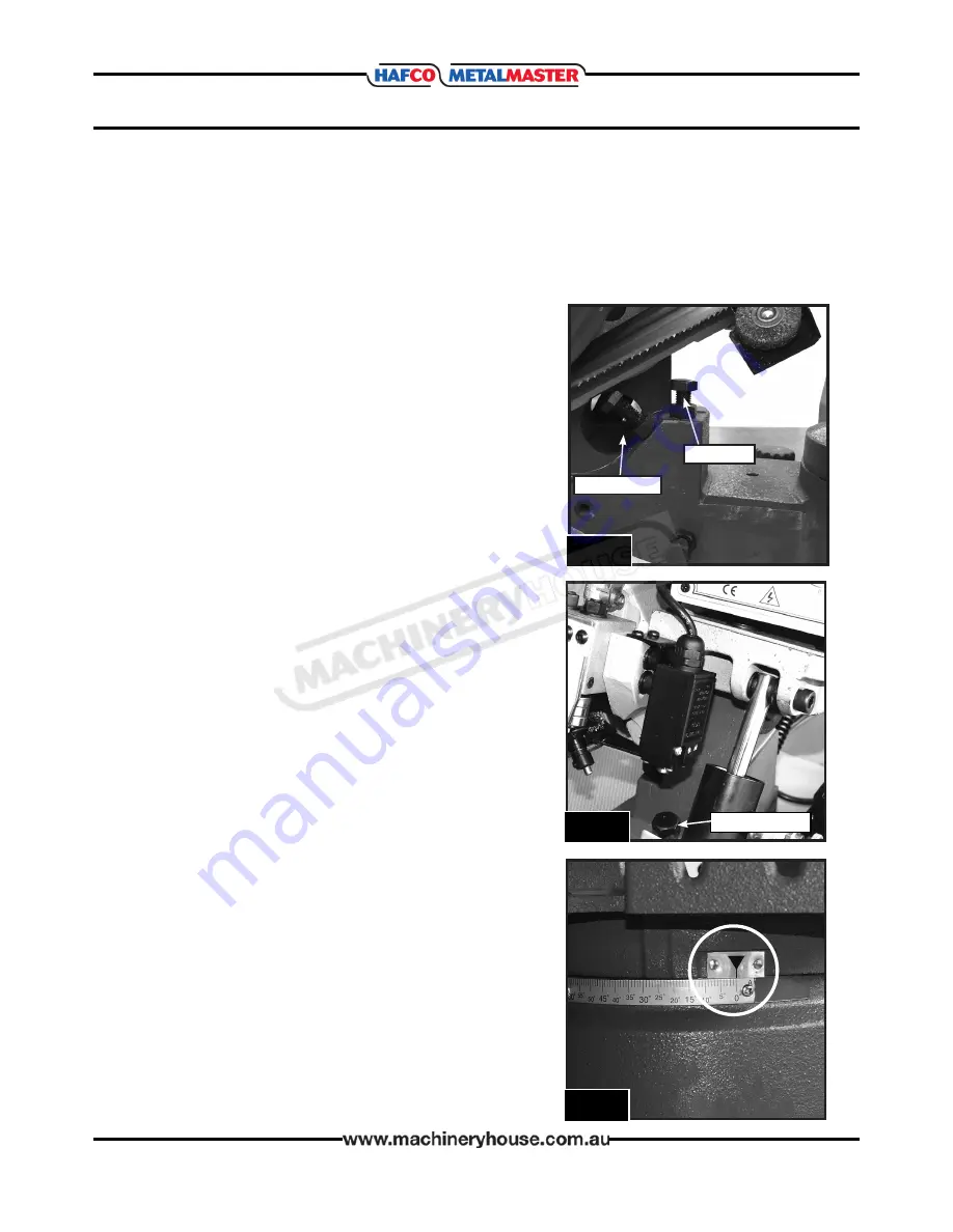
5.6 ADJUSTING THE FEED AUTO STOP

During adjustment of the blade guides it may be neces-

sary to remove the feed auto stop for better access.

If this has happened then the feed auto stop needs to be 

reset.

To adjust the feed auto stop.

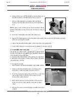
Undo the lock nut on the feed auto stop bolt and adjust 

the bolt so that the teeth on the band-saw blade are just 

below the vice table surface when the blade has finished 

the cut and the machine stops.( Fig.5.12)

Before any blade adjustment is made it may be necessary to adjust the feed stop. The blade 

should never rest or rub on any part of the vice casting.

The over tilt stop may also need to be adjusted to stop the saw bow from being able to lift past 

40°  causing the machine to be unstable.

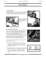
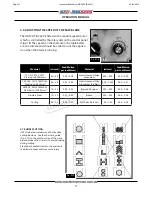
5.5 ADJUSTING FEED STOPS

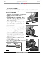
To Adjust the Feed Stop Bolt

1.   Disconnect the machine from the power supply

2.   Release the lock nut on the Feed Stop bolt.(Fig.5.11)

3.   Adjust the feed bolt until the teeth on the saw blade  


are just below the vise table surface when the 


machine stops.

4.   Tighten the lock nut and run the machine cycle and  


check that the adjustment is correct.

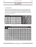
Head Swivel Scale

F

ig

. 5.13

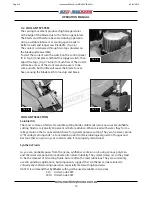
5.7 ADJUSTING THE HEAD SWIVEL STOPS

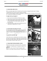
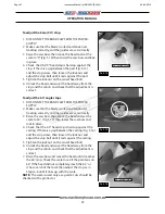
The head swivel stops are set by the factory, but due to 

shipping or continuing use, the stops may need to be 

adjusted.

NOTE:

 The scale is only to be used for approximate 

guide. For accurate setting a protractor should be used 

Feed Auto Stop

F

ig

. 5.12

Auto Feed Stop

F

ig

. 5.11

Feed Stop

Over Tilt Stop

Page 22

Instruction Manual for EB-260V (B062V)

04/04/2019

Summary of Contents for MetalMaster EB-260V

Page 1: ...HORIZONTAL BAND SAW OPERATION MANUAL Edition No EBS 001 Date of Issue 04 2019 Model EB 260V Order Code B062V Page 1 Instruction Manual for EB 260V B062V 04 04 2019 ...

Page 2: ...EL NO SERIAL NO DATE OF NOTE This manual is only for your reference Owing to the continuous improvement of the HAFCO machines changes may be made at any time without obligation or notice Please ensure the local voltage is the same as listed on the specification plate before operating this electric machine Distributed by www machineryhouse co nz MACHINE DETAILS Page 2 Instruction Manual for EB 260V...

Page 3: ...l Installation 11 3 6 Full Load Current Rating 12 4 OPERATION 4 1 Controls 12 4 2 Coolant System 14 4 3 Blade Guides 15 4 4 Setting The Down Feed 15 4 5 Setting The Cutting Angle 16 4 6 Adjusting The Speed Of The Saw Blade 17 4 7 Bundle Cutting 17 4 8 Blade Selection 18 5 MAINTENANCE 5 1 Schedule 19 5 2 Changing The Blade 19 5 3 Changing The Coolant 20 5 4 Blade Guide Adjustment 21 5 5 Adjusting F...

Page 4: ...m 950 Cutting Head Beam Type Manual Cutting Head Beam Return Manual Return Cutting Head Down Feed Control Adjustable Hydraulic Vice Clamping Fixture Manual Quick Action Bundle Cutting Fixture Blade Steps Speeds m min Variable 20 90 Blade Size L x W x T mm 2480 x 27 x 0 9 Motor Power kW hp 1 5 2 Voltage Amperage V amp 240 10 Nett Weight kg 200 1 1 SPECIFICATIONS 1 2 STANDARD EQUIPMENT q Machine sta...

Page 5: ...hown below to better understand the instructions in this manual A Blade Tension Handle E Motor I Stand B Lifting Handle F Ball Bearing Guide J Head Lock C Saw Bow G Coolant Pump K Vice D Control Panel H Length Stop L Quick Action Handle A B C D E F H G I K J L Page 5 Instruction Manual for EB 260V B062V 04 04 2019 ...

Page 6: ...y includes but is not limited to proper installation in a safe environment personnel training and authorization to use proper inspection and maintenance manual availability and comprehension of the application of the safety devices integrity and the use of personal protective equipment The manufacturer will not be held liable for injury or property damage from negligence improper training machine ...

Page 7: ...ris Make sure they are properly installed undamaged and working correctly FORCING MACHINERY Do not force the ma chine It will do the job safer and better at the rate for which it was designed NEVER STAND ON MACHINE Serious injury may occur if the machine is tipped or if the cutting tool is unintentionally contacted STABLE MACHINE Unexpected movement during operation greatly increases risk of injur...

Page 8: ...and lock it in the upward position q Set the angle of the vice or check it to ensure its squareness q Clamp workpiece firmly into the vice Long material must be supported q Adjust blade guards to cover unused portion of blade q Ensure hands are away from the blade and then turn the machine on q Allow the upper head assembly to come down slowly until the teeth are cutting the material q Keep hands ...

Page 9: ...does not tip over Check that the lifting slings do not interfere with the hydraulic pipes or electrical con duits Failure to follow these instructions could cause damage to the machine When the slings are at a 45 angle then each sling is carrying the equivalent of 50 of load weight Fig 2 1 When the slings are at a 90 angle then each sling will have a weight equal to 75 of the load on each sling Fi...

Page 10: ...fely Consideration should be given to the installation of auxiliary equip ment Leave enough space around the machine to open or remove doors covers as required for the maintenance and service as described in this manual It is recommended that the machine is anchored to the floor to prevent tipping or shifting It also reduces vibration that may occur during operation The machine should be mounted o...

Page 11: ...le Phase Power Supply Circuit 10 Amps Full Load Current 6 0 Amps Full load current rating is also on the specification plate on the motor 3 4 MACHINE LEVELING To set your machine up so that it operates to optimum performance apply the following procedure After your machine has been anchored to a concrete slab floor it then needs to be leveled Loosen the hold down bolts and place a level on the sur...

Page 12: ...e motor and circuitry This is especially true if connected to an undersized circuit or a long extension lead To reduce the risk of these hazards avoid overloading the machine during operation and make sure it is connected to a power supply circuit that meets the requirements 3 6 FULL LOAD CURRENT RATING 4 OPERATION 4 1 CONTROLS FIG 4 1 Fig 4 1 A B C D E A OFF Button When pressed the motor and blad...

Page 13: ...band saw is fitted with a quick action vise that allows for the quick tightening or releasing of material in the vise The quick action has a limited stroke so the hand wheel is required to move the vise jaws closer together Fig 4 3 Fig 4 3 Quick Action Lever LENGTH STOP The machine is fitted with an adjustable length stop Fig 4 5 To install the length stop 1 Screw the threaded rod into the base of...

Page 14: ...ulsifiable cutting fluids are typically 50 percent oil before dilution When mixed with water they form a milky emulsion that is an excellent choice for general purpose cutting They are however prone to Monday morning stink a foul smelling odor from microbiological growth of fungus and bacteria that can grow in your coolant sump if not properly maintained Synthetic Fluids As you can probably guess ...

Page 15: ...raise the bow to the highest position and hold it in place with the feed ON OFF lever Fig 4 11 Adjust the feed rate dial to the desired feed rate Start the saw and coolant pump and begin cutting Examining the chips is the best indication of the correct blade speed and feed rate A This is the correct chip shape The chip should be a silver colour If the chips are blue then decrease the feed until th...

Page 16: ... the scale Fig 4 13 is for reference only and if the angle is required to be very accurate then the angle should be checked with a protractor after the cut Fig 4 16 Fig 4 15 Fig 4 17 Fig 4 13 Fig 4 12 Fig 4 14 60 Stop To Swivel The Head To 60 Degrees Move the swivel lock lever Fig 4 12 to the right to release the head then swivel the head until the pointer is on 60 Fig 4 15 The swivel head of the ...

Page 17: ...erials 60 150 0 04 0 08 2 2 2 4 6 ADJUSTING THE SPEED OF THE SAW BLADE Fig 4 18 The HAFCO EB 260V is fitted with a variable speed motor which is controlled by the rotary dial on the control panel Fig 4 18 The speeds on the dial and in the table below are an estimate and should be varied to suit the applica tion when the blade is running CORRECT INCORRECT 4 7 BUNDLE CUTTING HAFCO does not recommend...

Page 18: ... 3 4 121 200 3 1 3 Over 200 2 or 1 25 1 4 2 or 0 8 1 3 Wall Thickness mm Outside diameter of tube or maximum profile section length mm 20 40 60 80 100 120 150 200 300 500 600 700 800 2 14 14 14 14 14 14 10 14 10 14 8 12 8 12 6 10 5 8 5 8 3 14 14 10 14 10 14 10 14 10 14 8 12 8 12 6 10 6 10 5 8 5 8 5 8 4 14 14 10 14 10 14 8 12 8 12 6 10 6 10 5 8 5 8 4 6 4 6 4 6 5 14 10 14 10 14 8 12 8 12 6 10 6 10 5...

Page 19: ...way from the lower blade guide 5 Remove the blade guard on the movable roller guide by removing the two button head cap screws Fig 5 3 Fig 5 1 ON OFF Lever Feed Rate Dial 5 1 SCHEDULE For the best performance of the machine follow the instructions given in this section and fol low the schedule laid out below Daily Check q Loose mounting bolts q Damaged saw blade q Correct blade tension q Cutting f...

Page 20: ...rrectly 5 3 CHANGING THE COOLANT Fig 5 5 This band saw is fitted with a coolant system that extends the life of the band saw blade by lowering the temperature of the blade and the workpiece To maintain the effectiveness of the cutting it is important to keep the coolant clean therefore the coolant should be changed every 1000 hrs To change the coolant 1 DISCONNECT THE MACHINE FROM THE POWER SUPPLY...

Page 21: ... back of the blade just touches the bearing making sure the guide housing is not tilted 5 Tighten the cap screws NOTE To access the cap screws on the other blade guide you will need to remove the two Phillips head screws and move the limit switch and its bracket out of the way To adjust the side bearings 1 Loosen the lock nut on the top of eccentric bolt 2 Using a spanner on the hex section betwee...

Page 22: ... stop the saw bow from being able to lift past 40 causing the machine to be unstable 5 5 ADJUSTING FEED STOPS To Adjust the Feed Stop Bolt 1 Disconnect the machine from the power supply 2 Release the lock nut on the Feed Stop bolt Fig 5 11 3 Adjust the feed bolt until the teeth on the saw blade are just below the vise table surface when the machine stops 4 Tighten the lock nut and run the machine ...

Page 23: ...orrectly and the guides are set correctly 3 Raise the saw bow then move the head and set the scale to 60 Fig 5 15 then lower the saw bow and lock in place 4 Check that the 60 head stop is hard up against the casting If there is a gap between the casting Fig 5 16 and the stop screw then loosen the lock nut and adjust the stop bolt until it rests against the casting 5 Tighten the lock nut on the swi...

Page 24: ... 2 The blade T P I is too great for the material 1 Reduce the feed rate 2 Check for the correct blade Page 16 Blades Breaking 1 Blade is not tension correctly 2 Loose work piece 3 The feed or cutting speed is wrong 4 Incorrect blade selection 5 The blade is too thick or low quality 1 Check the blade tension Page 13 2 Re clamp the work piece tighter or use a jig 3 Adjust the feed rate and the speed...

Page 25: ...chine 2 A scanned copy of your parts list diagram with required spare part s identified 3 Go to www machineryhouse com au contactus and fill out the inquiry form attaching a copy of scanned parts list SAW BLADE DOES NOT CUT SQUARE Check to see if the saw blade is cutting square If the blade is not cutting square as per the example Fig 5 17 1 Replace with a new blade and check for squareness The wo...

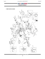
Page 26: ...26 OPERATION MANUAL SPARE PARTS DIAGRAM Page 26 Instruction Manual for EB 260V B062V 04 04 2019 ...

Page 27: ...61 62 63 64 65 67 68 69 70 71 72 73 74 75 76 77 78 79 80 81 82 83 84 85 86 87 89 90 91 92 93 94 95 96 97 98 99 100 C ring C Hex Nuts Blade Steel Shaft Block Blade Tension Handle Lever Vice Screw R Blade guard Vice Spring Vice lever Bearing Bearing Cover Vice Hand Wheel Spring Spring Connection Revolving Arm Rod Stop Bolt Micro Switch optional Block Hex Nuts Rubber Connection Arm Bolt Blade Guard H...

Page 28: ...28 OPERATION MANUAL EB 260V ELECTRICAL DIAGRAM Page 28 Instruction Manual for EB 260V B062V 04 04 2019 ...

Page 29: ...Micro Switch Haily CE T03 M2 Pump Motor George CE T04 ON I Switch Tend CE T05 OFF O Switch Tend CE T06 EMS Emergency Stop Demex CE T07 VR Converter VR George CE T08 Coolant Pump Switch Tend CE T09 M1 Main Motor George CE EB 260V ELECTRICAL PARTS LISTS Page 29 Instruction Manual for EB 260V B062V 04 04 2019 ...

Page 30: ... connecting 14 Use correct amperage extension cords Undersized extension cords overheat and lose power Replace extension cords if they become damaged 15 Keep machine well maintained Keep blades sharp and clean for best and safest performance Follow instructions when lubricating and changing accessories 16 Keep machine well guarded Make sure guards on machine are in place and are all working correc...

Page 31: ...controls Make sure you understand the use and operation of all controls 9 Power outage In the event of a power failure during use of the bandsaw turn off all switches to avoid possible sudden start up once power is restored 10 Work area hazards Keep the area around the bandsaw clean from oil tools chips Pay attention to other persons in the area and know what is going on around the area to ensure ...

Page 32: ...ecommended for Purchase Buyer User Secure support Long heavy material Eliminate avoid loose clothing Long hair etc Wear gloves when changing blades Check blade tracking before starting Blade guide system should be adjusted to suit material width MEDIUM Wear safety glasses Isolate power to machine prior to changing belts or maintenance Stand clear of machine when in operation MEDIUM ELECTRICAL F ST...

Reviews: