4
IV. Installation Steps(Fig.1-16)
The installation diagram is only for reference. The product is subject to the real object.
Prepare and check
the following tools.
Drill
Goggles
Spanner
Ruler
Spirit level
Philips screwdriver
Pencil
Teflon tape
Wrench
Hot water
Cold
water
Pipe joint
Lay cold and hot inlet pipes at proper height
on the wall, the inlets must be connected for
hot left and cold right. Otherwise thermostatic
cartridge will malfunction, or even cause
scalding. The center distance is 150mm.
Flow water to get rid of the debris in pipes.
Lay cold and hot inlet pipes at proper height on
the wall, the inlets must be connected for hot left
and cold right. Otherwise thermostatic cartridge
will malfunction, or even cause scalding. The
center distance is 150mm. Flow water to get rid
of the debris in pipes
3
Summary of Contents for 589.35.005
Page 2: ......
Page 4: ...3 III Installation Diagram 2 ...
Page 14: ...13 Turn diverter handle right for 90 water flows from bath spout 12 ...
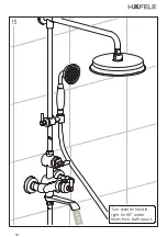
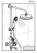
Page 15: ...14 Turn diverter handle left or right for 180 water flows from hand shower 13 ...
Page 17: ...16 Wrench Aerator 15 ...
Page 21: ...20 III Sơ đồ lắp đặt 19 ...
Page 31: ...30 Quay tay cầm lõi chuyển hướng sang phải 90o Cº nước chảy từ vòi tắm 29 ...
Page 32: ...31 Quay tay cầm lõi chuyển hướng sang trái hoặc phải 180ºo nước chảy từ tay sen 30 ...
Page 34: ...33 Đầu tạo bọt Chìa vặn 32 ...


