background image

50

L

RED

L

RED

R

BLUE

R

BLUE

3 mm

3 mm

Wie die Haken auf der Laufwagen zu bewegen

How to move the attachment of the upper slide

10

12

A920_Schiebetürantrieb_für_Slido_Flat_60_FB.indd   50

19.08.2019   07:54:44

Summary of Contents for 400.50.038

Page 1: ...732 24 084 HDE 07 06 2019 Schiebetürantrieb für Slido Flat 60 FB 400 50 038 Set e drive for Slido Flat 60 FB 400 50 039 A920_Schiebetürantrieb_für_Slido_Flat_60_FB indd 1 19 08 2019 07 54 24 ...

Page 2: ...ren Bereich des Möbels ablagern Werden diese Hinweise nicht beachtet kann es zu irreparablen Schäden am System und zu einer Gefährdung des Anwenders kommen System Nutzungsumgebung Das System wurde nach DIN 60335 für den häuslichen Gebrauch konzipiert gefertigt und geprüft und ist daher mit den in dieser Norm geforderten Sicherheitseinrichtungen ausgestattet Das Gerät bei Temperaturen nutzen die mi...

Page 3: ...ermitgeliefertenEinheitenüberprüftundeingestelltwerden AndereSteuerungendeselektrischen oder mechanischen Systems können zu schweren elektrischen und mechanischen Gefahren führen Hinweise zur Manipulierung des Systems Vor jeder Tätigkeit am System muss man die Einheit von der Stromversorgung isolieren Sicherstellen dass die Steuerungseinheit nicht nur während der Installation sondern auch während ...

Page 4: ...2 Grenzwerte Grenzwerte für Oberschwingungs ströme Geräte Eingangsstrom 16 A pro Phase CEI EN 61000 3 3 2013 Elektromagnetische Verträglichkeit EMV Teil 3 3 Grenzwerte Begrenzung von Spannungsänderungen Spannungsschwankungen und Flicker in öffentlichen Niederspannungs Versorgungsnetzen für Geräte mit einem Bemessungsstrom 16 A je Leiter die keiner Sonderanschlussbedingung unterliegen IEC 61000 3 3...

Page 5: ... forbidden Failure to respect this indication can irreversibly damage the system and determine a dangerous condition for the user Use environment of the system System is designed realized and tested for domestic use in accordance with DIN 60335 The system is realized with all the safety equipment in accordance with DIN 60335 Keep the system at a use temperature compatible with domestic environment...

Page 6: ...ry to ensure the right functioning and prevent wrong installation Control unit restrictions The control and adjustement of the motion trasmission must be operated only by the supplied control units Other uses of the mechanical and electrical parts can generate electric and mechanical severe risks Use warning Before any operation out of normal use on system unplug the power unit of the system from ...

Page 7: ...issions equipment input current 16 A per phase IEC 61000 3 2 EN 61000 3 3 2013 Electromagnetic compatibility EMC Part 3 3 Limits Limitation of voltage changes voltage fluctuations and flicker in public low voltage supply systems for equipment with rated current 16 A per phase and not subject to conditional connection IEC 61000 3 3 EN 301 489 1 V2 1 1 ElectroMagnetic Compatibility EMC standard for ...

Page 8: ...igung vornehmen All dimensions in this leaflet are stated in millimeters WARNING Do not use any anti friction oil or grease or thread realese spray on ball bearing or on wheels with O ring it can cause the melting of the inside ball bearing grease making them noisy or causing the break of the O ring of the wheels ABBREVIATIONS W width WA door width L length LB rail length D depth H height I distan...

Page 9: ...MIN LB 1782 MIN 8 LB 2WA X 2S WA LB X 2S 2 5 X 2 MIN X 2 MIN X 2 MIN WA 888 MIN LB 1782 MIN 8 LB WA 3X WA LB 3X 2 min 890 max 1800 min 888 max 1800 A920_Schiebetürantrieb_für_Slido_Flat_60_FB indd 9 19 08 2019 07 54 25 ...

Page 10: ...orderungen für die Türen Working requests for the doors 1a 16 9 128 196 128 125 WA 888 1000 51 86 5 128 9 128 86 5 16 32 128 51 12 12 32 128 L RED 50 A920_Schiebetürantrieb_für_Slido_Flat_60_FB indd 10 19 08 2019 07 54 25 ...

Page 11: ...hrungen der Türe zu machen der erste Bezugspunkt ist immer der Mittelpunkt der Tür unabhängig von ihrer Breite The starting reference for making the milling or drilling of the doors is always the center of the door whatever its width is A920_Schiebetürantrieb_für_Slido_Flat_60_FB indd 11 19 08 2019 07 54 25 ...

Page 12: ...12 2a 16 9 128 196 128 125 51 86 5 128 9 128 86 5 16 32 128 51 12 12 32 128 WA 888 1000 R BLUE 50 A920_Schiebetürantrieb_für_Slido_Flat_60_FB indd 12 19 08 2019 07 54 25 ...

Page 13: ...rungen der Türe zu machen der erste Bezugspunkt ist immer der Mittelpunkt der Tür unabhängig von ihrer Breite The starting reference for making the milling or drilling of the doors is always the center of the door whatever its width is A920_Schiebetürantrieb_für_Slido_Flat_60_FB indd 13 19 08 2019 07 54 25 ...

Page 14: ...14 Montageanleitungen Assembly instructions 1 2 A920_Schiebetürantrieb_für_Slido_Flat_60_FB indd 14 19 08 2019 07 54 26 ...

Page 15: ...15 3 A920_Schiebetürantrieb_für_Slido_Flat_60_FB indd 15 19 08 2019 07 54 26 ...

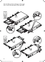
Page 16: ...16 4 A920_Schiebetürantrieb_für_Slido_Flat_60_FB indd 16 19 08 2019 07 54 26 ...

Page 17: ... 2 S 400 S S R BLUE d d WA 2 S 400 S S L RED Positionierung und Befestigung der oberen Aufschläge Positioning and fixing of the upper locks A920_Schiebetürantrieb_für_Slido_Flat_60_FB indd 17 19 08 2019 07 54 27 ...

Page 18: ...18 Ø5 5 6 mm 5 6 A920_Schiebetürantrieb_für_Slido_Flat_60_FB indd 18 19 08 2019 07 54 27 ...

Page 19: ...19 7 8 A920_Schiebetürantrieb_für_Slido_Flat_60_FB indd 19 19 08 2019 07 54 28 ...

Page 20: ...20 10 9 A920_Schiebetürantrieb_für_Slido_Flat_60_FB indd 20 19 08 2019 07 54 29 ...

Page 21: ...21 11 Schließen Sie den linken oberen Laufwerk bevor Sie das System befestigen Close the left upper slide before fixing the system A920_Schiebetürantrieb_für_Slido_Flat_60_FB indd 21 19 08 2019 07 54 29 ...

Page 22: ...12 13 Schließen Sie den rechten oberen Laufwerk bevor Sie das System befestigen Close the right upper slide before fixing the system A920_Schiebetürantrieb_für_Slido_Flat_60_FB indd 22 19 08 2019 07 54 30 ...

Page 23: ...23 14 15 A920_Schiebetürantrieb_für_Slido_Flat_60_FB indd 23 19 08 2019 07 54 30 ...

Page 24: ...24 16 17 18 19 A920_Schiebetürantrieb_für_Slido_Flat_60_FB indd 24 19 08 2019 07 54 31 ...

Page 25: ...WA 2 S 400 R S d S d WA 2 S 400 L S S d Positionierung und Befestigung der unteren Aufschläge Positioning and fixing of the lower locks A920_Schiebetürantrieb_für_Slido_Flat_60_FB indd 25 19 08 2019 07 54 31 ...

Page 26: ...26 20 21 A920_Schiebetürantrieb_für_Slido_Flat_60_FB indd 26 19 08 2019 07 54 32 ...

Page 27: ...ird N B The lower slide must be closed during the door hooking 35 mm 25 mm 17 mm Abstand zwischen der unteren Kante der Tür und den Boden Distance between the door and the floor 17 mm 25 mm 35 mm 22 3 mm A920_Schiebetürantrieb_für_Slido_Flat_60_FB indd 27 19 08 2019 07 54 32 ...

Page 28: ... 60 133 57 Die Schienen an den Schrank nach Ihrer Wahl befestigen 23a 23b Fix the rails on the wardrobe according to the choice 23a 23b 23a 23b A920_Schiebetürantrieb_für_Slido_Flat_60_FB indd 28 19 08 2019 07 54 33 ...

Page 29: ...29 35 17 35 25 70 24 A920_Schiebetürantrieb_für_Slido_Flat_60_FB indd 29 19 08 2019 07 54 33 ...

Page 30: ...30 3 mm Öffnen Sie den oberen Laufwagen vor dem Aufhängen der Tür Open the upper slide before hanging the door 25 26 A920_Schiebetürantrieb_für_Slido_Flat_60_FB indd 30 19 08 2019 07 54 34 ...

Page 31: ... the vertical alignment and the central distance between the doors eventually move the upper Left or Right locks 8 mm 28a Schließen Sie die Tür Stellen Sie die Hohe der Tuer und bringen Sie mit der oberen Schiene bündig Close the door Adjust the level of the door aligning it with the upper rail DOOR RAIL A920_Schiebetürantrieb_für_Slido_Flat_60_FB indd 31 19 08 2019 07 54 35 ...

Page 32: ...32 8 mm Anhaken die untere Fuehrung an der Tür und die Schraube befestigen Hook the lower slide and fix the screws 8 mm 28b 29 A920_Schiebetürantrieb_für_Slido_Flat_60_FB indd 32 19 08 2019 07 54 36 ...

Page 33: ...33 Schrank konfiguration Wardrobe configurations 1 1 1 4 2 3 A E F 34 38 42 A920_Schiebetürantrieb_für_Slido_Flat_60_FB indd 33 19 08 2019 07 54 36 ...

Page 34: ...34 A 1 1 KONFIGURATION CONFIGURATION A920_Schiebetürantrieb_für_Slido_Flat_60_FB indd 34 19 08 2019 07 54 36 ...

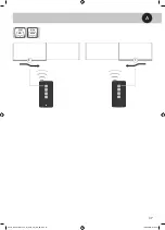
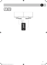
Page 35: ...35 A 1 1 1 1a A920_Schiebetürantrieb_für_Slido_Flat_60_FB indd 35 19 08 2019 07 54 37 ...

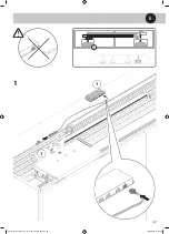
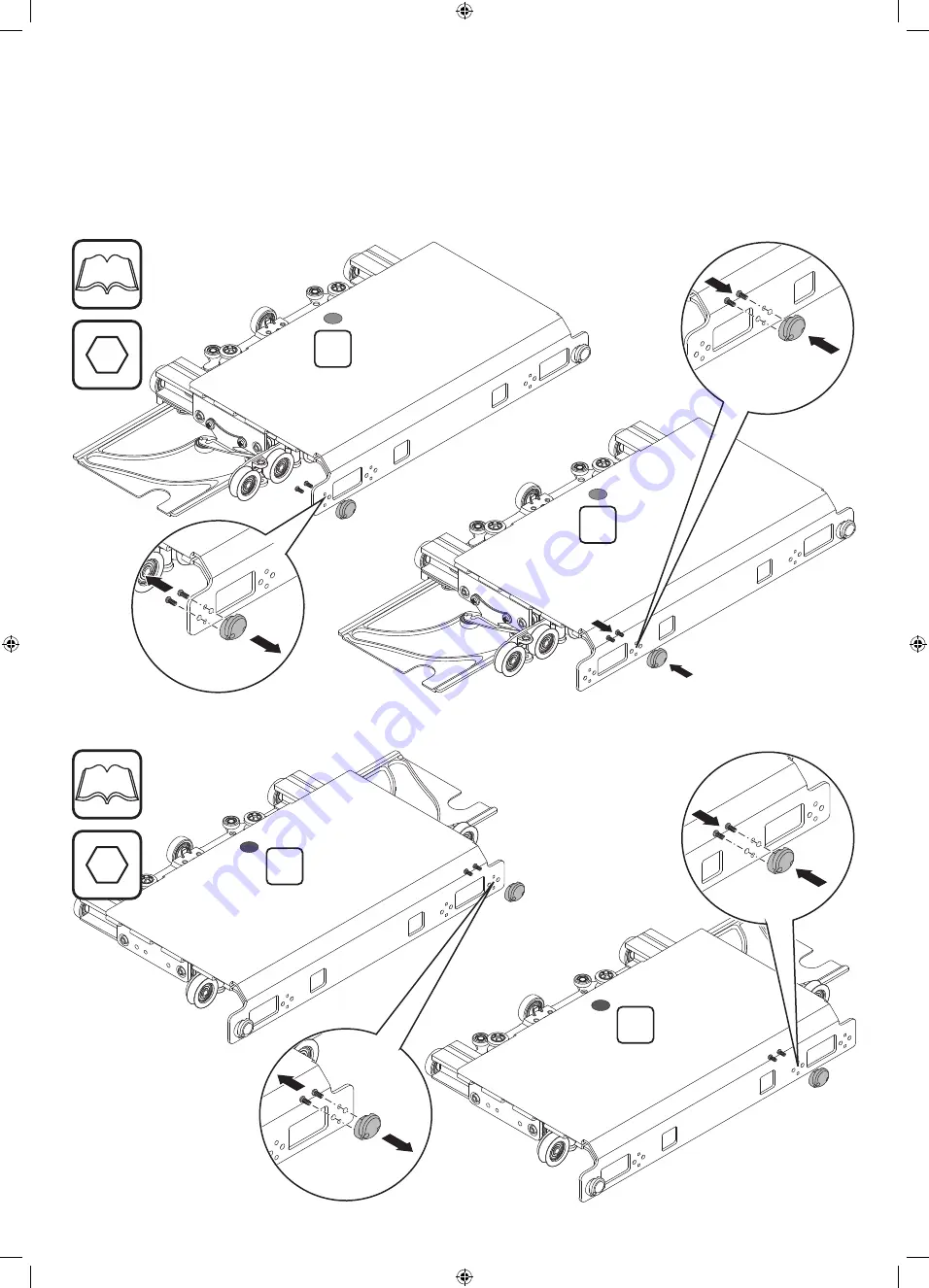
Page 36: ...36 A 1 1 1 1b A920_Schiebetürantrieb_für_Slido_Flat_60_FB indd 36 19 08 2019 07 54 37 ...

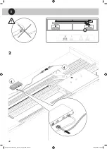
Page 37: ...37 A 1 1 EN 59 DE 51 A920_Schiebetürantrieb_für_Slido_Flat_60_FB indd 37 19 08 2019 07 54 37 ...

Page 38: ...38 E KONFIGURATION CONFIGURATION 1 4 A920_Schiebetürantrieb_für_Slido_Flat_60_FB indd 38 19 08 2019 07 54 38 ...

Page 39: ...39 E 1 1 1 1 A920_Schiebetürantrieb_für_Slido_Flat_60_FB indd 39 19 08 2019 07 54 38 ...

Page 40: ...40 E 4 4 2 4 A920_Schiebetürantrieb_für_Slido_Flat_60_FB indd 40 19 08 2019 07 54 39 ...

Page 41: ...41 E 1 4 EN 59 DE 51 A920_Schiebetürantrieb_für_Slido_Flat_60_FB indd 41 19 08 2019 07 54 39 ...

Page 42: ...42 F KONFIGURATION CONFIGURATION 3 2 A920_Schiebetürantrieb_für_Slido_Flat_60_FB indd 42 19 08 2019 07 54 39 ...

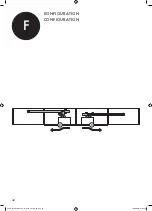
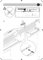
Page 43: ...43 F 2 2 2 1 A920_Schiebetürantrieb_für_Slido_Flat_60_FB indd 43 19 08 2019 07 54 40 ...

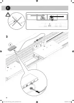
Page 44: ...44 F 3 3 3 2 A920_Schiebetürantrieb_für_Slido_Flat_60_FB indd 44 19 08 2019 07 54 41 ...

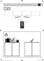
Page 45: ...45 F 3 2 EN 59 DE 51 A920_Schiebetürantrieb_für_Slido_Flat_60_FB indd 45 19 08 2019 07 54 41 ...

Page 46: ...46 Sichern Sie den Kabelbaum Hold wiring A920_Schiebetürantrieb_für_Slido_Flat_60_FB indd 46 19 08 2019 07 54 42 ...

Page 47: ... Verfahren fertig ist befestigen Sie nochwieder die Stopper Müssen Sie die Tür noch wieder justieren Do You need to re adjust the door Do not forget to unlock the lower and upper stops before any further doors adjustment 1 Slightly shake 2 the door at the bottom with both hands in this way the bottom stop will align automatically to the top stop Lock the stops when finished A920_Schiebetürantrieb_...

Page 48: ...48 8 mm 1 Wie die Türen entfernen How to remove the doors 2 4 mm DOOR RAIL A920_Schiebetürantrieb_für_Slido_Flat_60_FB indd 48 19 08 2019 07 54 43 ...

Page 49: ...49 4 3 mm 3 A920_Schiebetürantrieb_für_Slido_Flat_60_FB indd 49 19 08 2019 07 54 44 ...

Page 50: ... L RED L RED R BLUE R BLUE 3 mm 3 mm Wie die Haken auf der Laufwagen zu bewegen How to move the attachment of the upper slide 10 12 A920_Schiebetürantrieb_für_Slido_Flat_60_FB indd 50 19 08 2019 07 54 44 ...

Page 51: ...gungsschiene mit der Kontrolleinheit geliefert 1 3 Installationsfunktionen Teachen des Türhubs Das System besitzt eine spezifische Funktion zur Erkennung des Türendschalters versehen Nach der Installation des Systems kann man diese Funktion durch den längeren Druck 3 Sekunden der Taste SET RESET auf der Steuerungseinheit einschalten Vor der Inbetriebnahme dieser Funktion müssen die mechanische End...

Page 52: ...otwendig Sollte es während der Bewegung einer Tür zu einem Stromausfall kommen stoppt das System Wird das Netz wieder angeschlossen bewegt sich die Tür langsam bis zum vollständigen Schließen am Ende dieses Verfahrens ist das System erneut betriebsbereit 1 11 Von der Steuerungseinheit gesteuerter Switch Die Steuerungseinheit ist mit einem N O Switch versehen der immer dann einen Kontakt schließt w...

Page 53: ...erwendete System verwenden muss 3 3 Hub Registrierungszyklus SET RESET 00 00 03 DieinPunkt2 3beschriebeneFunktionzurautomatischen Erkennung der Türendschalter durch Drücken und Halten 3 Sekunden der Taste SET RESET an der Steuerung starten Ab diesem Punkt werden sich alle Türen eine nach der Anderen ab der ersten linken Tür des Schranks mit reduzierter Geschwindigkeit zu den entsprechenden Endscha...

Page 54: ... annullieren die Taste REMOTE SET drücken und loslassen danach beginnt die LED zu blinken Erneut die Taste REMOTE SET drücken und gedrückt halten bis die LED nicht mehr blinkt Lässt man die Taste los wird die rote LED 5 Mal blinken und bestätigt so die Aufhebung der vorab durchgeführten Verbindungen Das Verfahren zur Aufhebung der Verbindung der Fernbedienung eliminiert jeden vorherigen Speicherpl...

Page 55: ...s Schließen verhindert wird Diese Kontrolle ist durchzuführen um Risiken oder Schäden oder einen eventuellen Defekt oder eine Funktionsstörung des Systems zu verhindern 4 1 Öffnen einer Tür Die Türöffnungssteuerung kann durch einen manuellen Input oder mit der Fernbedienung gegeben werden Die Tür einige Millimeter in die Öffnungsrichtung drücken das System erkennt automatisch die Bewegung und betä...

Page 56: ...Interne Reinigung des Systems Die interne Reinigung des Systems darf nur von Fachpersonal durchgeführt werden Das System ist so konzipiert dass es auch bei Staubablagerungen im Inneren des Systems funktioniert jedoch ist die Entfernung von Schmutz oder Fremdkörpern aus dem Inneren des Systems mit einem Druckluftstrahl möglich Die Demontage der Handhabungsgeräte ist verboten im gegenteiligen Fall h...

Page 57: ...ellierung des Möbels wie die Montage des damit verbundenen Schiebesystems kontrollieren Am Schiebesystem muss man kontrollieren dass die Regulierungen richtig durchgeführt wurden und dass keine Reibungen zwischen den festen teilen des Schranks und den Gleitschuhen oder den Türen bestehen Die Ebenheit der Türen prüfen sollte die Türstruktur keine perfekte Ebenheit der Tür garantieren sollte man ein...

Page 58: ...as Teach Verfahren der Endschalter starten indem man die Taste SET RESET 3 Sekunden drückt 6 6 Das Gerät z B Licht im Schrank das mit dem Switch verbunden ist funktioniert nicht erwartungsgemäß Die korrekte Verkabelung des Geräts kontrollieren wie im Punkt 3 5 beschrieben Der Switch liefert keine Spannung am Ausgang und dient als einfacher Schalter Einen der 2 Versorgungspole an den Switch anschli...

Page 59: ...ing the movement bars 1 3 Installation features door track self learning The system is equipped with a specific function for setting door track limits After the system is installed this function can be activated by pressing the SET RESET button on the control unit for 3 seconds Before activating this function ensure that the supplied mechanical track limit stops are positioned according to instruc...

Page 60: ... movement of a door the system will stop When powered again the door will move slowly to its closed position before the system becomes fully operational again 1 11 Control unit switch The control unit is equipped with a NO switch that closes its contact every time a door is commanded to open The switch can handle voltages of between 0 and 48 V and a maximum current of 2A 2 1 Prerequisites 2 2 Elec...

Page 61: ...the function for automatic detection of door track limits as described in Section 2 3 by long pressing 3 seconds the SET RESET button on the control unit One door at a time starting from the first door to the left of the cabinet the doors will move slowly towards their respective track limit stops The operation may take up to a few minutes until all door tracks have been memorized During this set ...

Page 62: ... the led stops flashing When the button is released the red LED will flash 5 times to confirm the unpairing The unpairing of a remote control completely eliminates its association with any control unit In order to use the remote control it will be necessary to pair it again using the standard procedure 3 5 Wiring of the control unit switch The NO switch is a simple normally open contact controlled...

Page 63: ...ecks in order to avoid any risk damage or injury due to possible faults or malfunctioning of the system 4 1 Door opening The door opening command can be given by slightly pushing on the door or by using the remote control Push the door a few millimetres in its opening direction and the system will automatically detect the displacement and operate the motor until the door reaches its open position ...

Page 64: ...ystem and aluminium tracks a dry cloth or alternatively compressed air should be used 5 3 System interior cleaning Internal cleaning of the system must only be performed by qualified personnel The system is designed to work even if dust is deposited inside However the removal of debris or foreign material from inside the system may be performed by using a jet of compressed air It is prohibited to ...

Page 65: ... and sliding pads or doors Check the levelling of the doors If the structure of the door does not guarantee perfect levelling the installation of a tensioner to straighten the doors is recommended Check that there are no physical obstacles in the path of the door Check that the system s wiring is not in the path of the door or of the door to movement bar connection Finally unplug and re plug the c...

Page 66: ...emember that the switch does not supply an output voltage and acts as a simple switch Connect one of the 2 poles of the power supply to the switch to have the device controlled by the control unit Check that the device is compatible with a maximum power supply of 48V and absorbs a maximum current of 2 1A A920_Schiebetürantrieb_für_Slido_Flat_60_FB indd 66 19 08 2019 07 54 46 ...

Page 67: ...A920_Schiebetürantrieb_für_Slido_Flat_60_FB indd 67 19 08 2019 07 54 46 ...

Page 68: ...732 24 084 HDE 07 06 2019 Subject to alterations 2019 by Häfele GmbH Co KG Adolf Häfele Str 1 D 72202 Nagold www hafele com A920_Schiebetürantrieb_für_Slido_Flat_60_FB indd 68 19 08 2019 07 54 46 ...

Reviews: