


15
WARNING! Failure to install the screws or fixing device in
accordance with these instructions may result in electrical
hazards.
Do not use with a programmer, timer, separate remote control
system or any other device that switches on automatically.
When handling the hood do not put hands within the range of
action of the pull-out suction panel (trolley)
The hood is equipped with safety switches which inhibit
operation when the front filter panel is unhooked.
With the intention of constantly improving our products, we
reserve the right to make all the changes in their technical,
functional or design characteristics, deriving from their
evolution. In case of the version with external motor, the
normal operation of the hood requires the use of a suction unit
(external motor) of the same manufacturer.
This appliance is marked according to the European directive
2012/19/EC on Waste Electrical and Electronic Equipment
(WEEE). By ensuring this product is disposed of correctly, you
will help prevent potential negative consequences for the
environment and human health, which could otherwise be
caused by inappropriate waste handling of this product.
The symbol
on the product, or on the documents
accompanying the product, indicates that this appliance may
not be treated as household waste. Instead it should be taken
to the appropriate collection point for the recycling of electrical
and electronic equipment. Disposal must be carried out in
accordance with local environmental regulations for waste
disposal.
For further detailed information regarding the process,
collection and recycling of this product, please contact the
appropriate department of your local authorities or the local
department for household waste or the shop where you
purchased this product.
Appliance designed, tested and manufactured according to:
• Safety: EN/IEC 60335-1; EN/IEC 60335-2-31, EN/IEC
62233.
• Performance: EN/IEC 61591; ISO 5167-1; ISO 5167-3; ISO
5168; EN/IEC 60704-1; EN/IEC 60704-2-13; EN/IEC 60704-3;
ISO 3741; EN 50564; IEC 62301.
• EMC: EN 55014-1; CISPR 14-1; EN 55014-2; CISPR 14-2;
EN/IEC 61000-3-2; EN/IEC 61000-3-3. Suggestions for a
correct use in order to reduce the environmental impact:
Switch ON the hood at minimum speed when you start
cooking and kept it running for few minutes after cooking is
finished. Increase the speed only in case of large amount of
smoke and vapour and use boost speed(s) only in extreme
situations. Replace the charcoal filter(s) when necessary to
maintain a good odour reduction efficiency. Clean the grease
filter(s) when necessary to maintain a good grease filter
efficiency. Use the maximum diameter of the ducting system
indicated in this manual to optimize efficiency and minimize
noise.
Use
The hood is designed to be used either for exhausting or filter
version.
Ducting version
In this case the fumes are conveyed outside of the building by
means of a special pipe connected with the connection ring
located on top of the hood.
Attention
! The exhausting pipe is not supplied and must be
purchased apart.
Diameter of the exhausting pipe must be equal to that of the
connection ring.
Attention! If the hood is supplied with active charcoal filter,
then it must be removed.
Filter version
The aspirated air will be degreased and deodorised before
being fed back into the room.
In order to use the hood in this version, you have to install a
system of additional filtering based on activated charcoal.
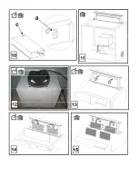
Note:
The recycled air in the charcoal filter is sent back to the
kitchen through a duct which conveys air on a side of the
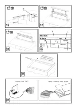
cabinet (
Picture 11
).
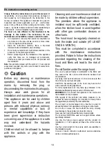
Non-return valve locking
Attention, before connecting the flexible air outlet pipe make
sure that the non-return valves of the suction unit can freely
rotate (
Picture 12
).
The models with no suction motor only operate in ducting
mode, and must be connected to an external suction device
(not supplied).
The connecting instructions are supplied with the peripheral
suction unit.
Installation
Note:
The installation must be performed so that accessibility
to the hood and its electronic components is always ensured
for possible technical assistance interventions.
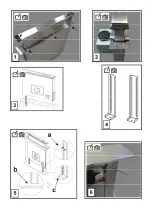
When installing the product, it is recommended to keep a
minimum distance of 400mm between the worktop and any
components laid on top of the hood.
This is to let the suction panel move upwards (opening) and
downwards (closing) without any obstacles, and to facilitate
access to the hood controls on the panel.
WARNING:
Put the metal box containing the electronic
components at a distance not shorter than 65 cm from the gas
hob or 65 cm from the hood suction point.
The minimum distance between downdraft edge and hob
edge must be at least 50mm.


