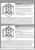
60
240
225
ZONA 1
ZONA 0
ZONA 2
ZONA 3
PREMESSA
L’installazione della
GENERATORE G-STEAM
deve essere eseguita da personale abilitato o qualificato, sia per quanto riguarda il collegamento
elettrico che quello idraulico. Prima di procedere al collegamento, l’installatore deve accertarsi che l’impianto elettrico sia conforme alle norme
CEI 64.8
, protetto da un interruttore differenziale 0,03A, e che l’impianto di messa a terra sia efficiente e conforme alle disposizioni sopracitate.
GENERATORE G-STEAM
deve essere fissata stabilmente e collegati in maniera fissa alla rete elettrica e all’impianto di terra. L’allacciamento alla
rete elettrica, deve essere fatto tramite un interruttore onnipolare con apertura dei contatti di almeno 3 mm, e posto fuori dalle zone di sicurezza
come previsto dalla norma tecnica
CEI 64-8/7
ultima edizione (esso deve essere installato in zone non raggiungibili dall’utente che sta usando
l’apparecchiatura) lontano da possibili spruzzi o erogazioni d’acqua. (vedi disegno) Il cavo per il collegamento all’impianto elettrico dovrà essere
protetto da un tubo corrugato che non deve avere giunzioni o connessioni intermedie. Il cavo non deve avere caratteristiche inferiori al tipo
H05VV-F la sua sezione deve essere dimiensionata in base al modello. I componenti usati per il collegamento devono avere caratteristiche e grado
di protezione IP come previsto dalle norme
64.8
per le applicazioni in bagni e docce.
ATTENZIONE:
VERIFICARE AL RICEVIMENTO DELLA MERCE LE CONDIZIONI DELL’IMBALLO E DEL
PRODOTTO, IN MODO PARTICOLARE SE L’IMBALLO PRESENTA DANNI VISIVI, FARLO
NOTARE DIRETTAMENTE AL TRASPORTATORE.LA DITTA COSTRUTTRICE DECLINA
OGNI RESPONSABILITÁ SUL TRASPORTO.
Si consiglia l’uso di guanti.Maneggiare con cura le parti delicate.
Verifi care le condizioni degli stessi prima di procedere all’installazione.
Prima di procedere all’installazione assicurarsi che gli attacchi predisposti siano
come da scheda tecnica del modello da installare. Assicurarsi inoltre che sia
garantita la perpendicolarità del muro.
COLLEGAMENTO EQUIPOTENZIALE
L’apparecchiatura va collegata all’impianto equipotenziale dello stabile tramite
l’apposito morsetto posto sul telaio debitamente segnalato, come previsto dalle
norme 60335.2.105.
IT
03
ZONA DI SICUREZZA
The
GENERATORE G-STEAM
must be installed by authorised or qualified personnel, both as regards the electrical and plumbing connections.
Before connecting the booth, the installer must make sure that the electrical system complies with
CEI 64.8
standards, the it is protected by a
differential switch 0.03A, and that the earthing system is effi cient and complies with the aforementioned provisions.
GENERATORE G-STEAM
must
be fi rmly secured and permanently connected to the electrical network and the earthing system.Connections to the electrical system must be made
with an omnipolar switch with a contact aperture of at least 3mm, placed outside the safety zones as set forth in the latest edition of technical
standard CEI
64-8/7
(it must be from splashes or the water supply (see drawing). The electrical system connection wire must be protected by a
corrugated tube with no joins or intermediate connections. The wire must not have characteristics inferior to those of type H05VV-F its section must
be sized according to the model. The components used for connection must have specifications and IP protection as set forth in standards
64.8
for
application in baths and showers.
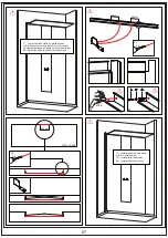
GB SAFETY ZONE
60
240
225
ZONA 1
ZONA 0
ZONA 2
ZONA 3
INTRODUCTION
WARNING:
CHECK THE CONDITION OF THE PACKAGING AND THE GOODS UPON
RECEIPT, ESPECIALLY IF THE PACKAGING SHOWS ANY VISIBLE DAMAGE. IF IT
DOES, POINT THIS OUT TO THE TRANSPORTER IMMEDIATELY.THE MANU-
FACTURER DECLINES ALL RESPONSIBILITY FOR TRANSPORT.
EQUIPOTENTIAL CONNECTION
The appliance should be connected to the earth system of the building by
means of the appropriate terminal located on the frame of the tray and
properly marked as set forth by
standards 60335.2.105.
We recommend the use of gloves.
Check the condition of these items prior
to proceeding with installation.
Before proceeding with installation, make sure that the connections match the
technical information of the model to be installed. Also make sure that the walls
above the shower tray are completely perpendicular.


