2942 Magnetic Lock
Installation Instructions
I-EA00054
Rev 2, Rev Date: 8/15/18
Always visit www.hagerco.com for the latest Installation Instructions
HAGER COMPANIES 139 Victor Street, St. Louis, MO 63104 • (800) 325-9995
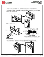
6. Holding the magnet housing at each end, engage the entire length of the interlock detail, by pushing towards the
door. Tap with a soft hammer to ensure proper alignment and engagement.
CAUTION: The lock body must be held in place until secured with mounting screws.
Secure socket head
screws provided inside the housing at each end. Start screws into threads carefully to avoid stripping the
threads. Check alignment and tighten screws. Pull wires through frame, mounting plate and magnet housing
STEP 6
7. Select jumper position for 12VDC or 24VDC. Connect power to magnetic
lock.
A/C
MAINS
POWER
SUPPLY
12VDC
or
24VDC
SWITCH or
ACCESS
CONTROL
+
-
8. Test operation. When all is operating properly, tighten
all screws as shown. Install security pins and screws
as shown. Install anti-tamper plugs over socket head
screws using a soft hammer to avoid damage to the housing.
ATTACH THE RED SIDE OF THE CONNECTOR HERE
FOR A GREEN LED ENERGIZED & SECURE (RED=ENERGIZED & UNSECURE)
ATTACH THE GREEN SIDE OF THE CONNECTOR HERE
FOR A RED LED ENERGIZED AND UNSECURE (GREEN=ENERGIZED & SECURE)
COM
NC
NO
Door Position Sensor (Reed switch)
ORG (open with door closed)
YEL (closed with door closed)
WHT
R
G
B
W
G
B
R
Door
Position
Sensor
Lock
Status
Switch
(Relay)
Power
Supply
Voltage Jumper
8
N
C
7
C
6
N
O
5
N
C
4
C
3
N
O
2
-
1
+
12VDC
24VDC
LED
RED
GRN
Page 3 of 4


