3500 Series ANSI Grade 2 Lever Set
Installation Instructions
Meets ANSI 156.2
I-LS00768
For use on doors 1-3/8” to 2” (35 mm - 51 mm) thick
REV 2
Page 1 of 2
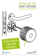
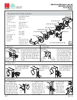
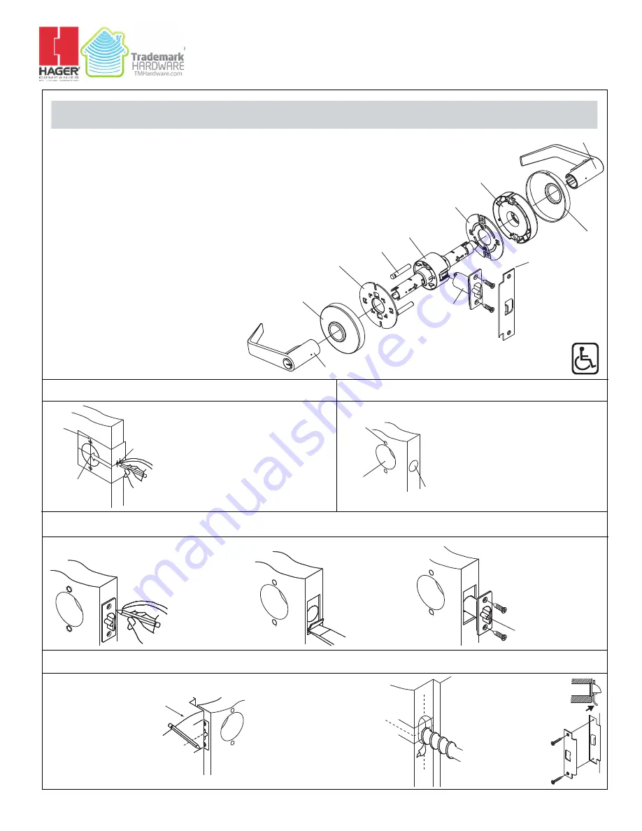
1. MARK DOOR
TOOLS REQUIRED FOR
NEW INSTALLATION:
(1) Phillips Head
Screwdriver
(1) 2-1/8” (54 mm) Hole
Saw
(1) 1” (25.4 mm) Drill Bit
(1) 5/16” (8 mm) Drill Bit
(1) Chisel
(1) Catch-Release Tool
(Provided)
TOOLS REQUIRED FOR
REPLACEMENT
INSTALLATION:
(1) Phillips Head
Screwdriver
FOR REMODELING OR NEW
CONSTRUCTION:
-Follow all steps
FOR REPLACEMENT OF
EXISTING LOCK:
-Follow steps 3C, 4C, 5
through 9 after removal of
old lock
FOR CYLINDER
REPLACEMENT:
-Follow Step 10
NOTE:
Failure to install thru-bolts
and removable screw posts
voids BHMA certification,
UL rating, and warranty.
Measure center line of lock; height as
desired from finished floor. Select 2-3/4”
or optional 2-3/8” backset, fold and apply
template to high side of door bevel and
mark center of door edge as indicated on
template. Mark center hole and screw-
post holes on door face through guide on
template.
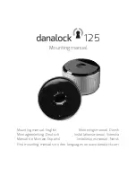
2. DRILL HOLES
Drill 2-1/8” (54 mm) hole through
door face as marked for lockset.
(It is recommended that holes be
drilled from both sides on wood
doors to prevent splitting.) Drill
5/16” (8 mm) holes for screw-
posts. Drill 1” (25.4 mm) hole in
center of door edge for latch.
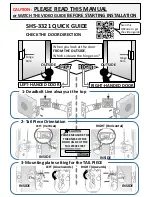
3. INSTALL LATCH
A. Insert latch in hole keeping
it parallel to face of door. Mark
outline of latch face plate and
remove latch.
B. Chisel 5/32” (4
mm) deep or until latch
face plate is flush with
door edge.
C. Insert latch and tighten
to the door using #8 screws.
NOTE: Latchbolt bevel must
face to closing direction.
4. INSTALL STRIKE
A. Close door until
latchbolt touches jamb.
Locate strike in jamb and
center line of strike. Open
door and extend line to door
stop. Measure one half of
door thickness plus 1/8”
from door stop. Vertically
mark center line for strike.
B Drill two (2) 1” (25.4
mm) holes 3/4” (19 mm)
deep in door jambs 5/16” (8
mm) above and 5/16“ (8
mm) below horizontal center
line. CAUTION: To ensure
proper lockset function, hole
in jamb must be drilled a full
3/4” (19 mm) deep.
C. Cut out jamb
mortise for strike
3/32” (2.4 mm)
deep or until strike
is flush with jamb.
Tighten screws.
Latch stops against
strike, as illustrated.
CENTER
LINE
MARK FOR 2-1/8”
(54 mm) HOLE ON
DOOR FACE
MARK FOR 1”
(25.4 mm)
HOLE IN
DOOR EDGE
2-1/8” (54 mm)
HOLE FOR
LOCKSET
5/16” (8 mm)
HOLE FOR SCREW
POST
1” (25.4
mm) HOLE
FOR LATCH
JAMB
CENTER
LINE
5/16”
CL
5/16”
CL
LATCH
STRIKE
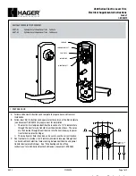
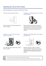
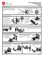
INSIDE LEVER
INSIDE ROSE LINER
INSIDE MOUNTING PLATE
LOCK BODY ASSEMBLY
REMOVABLE SCREW POST
OUTSIDE MOUNTING PLATE
OUTSIDE ROSE
OUTSIDE LEVER
LATCH
ASA STRIKE
INSIDE ROSE
(ILLUSTRATION: ENTRANCE FUNCTION)