

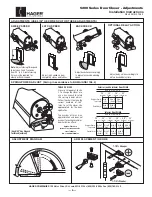
Rota
te 45˚
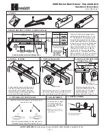
3-1/2"
(89mm)
3/4"
(19mm)
12"
(305mm)
Top of
Door
B
Frame
(Center on Hinge)
(Center on Hinge)
2-3/4"
(70mm)
7/16"
(11mm)
2"
(51mm)
A
3/8"
(10mm)
1/2"
(13mm)
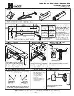
Speed regulating valves toward lock stile.
CONNECTING ROD
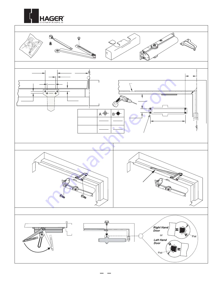
1. PARTS
3. INSTALL CLOSER
2. MARK AND DRILL HOLES (
Right Hand Shown)
4. INSTALL CONNECTING ROD
5. INSTALL MAIN ARM
Select hand of door and the degree of door
opening. Fold template on the corresponding line
for desired degree and hand. Fold or cut upper
corner illustrated on template and align template
with the hinge edge of door. At the “Frame Stop
Line” fold toward you and attach template to door.
Mark, prep and drill/tap 1/4"-20 holes for closer
body and parallel arm bracket mounting screws.
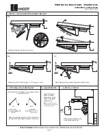
Use adjustable wrench to rotate spindle 45˚ counterclockwise for Right Hand
Door or clockwise for Left Hand Door. Place main arm on spindle so that the
“R” (Right Hand Door) or “L” (Left Hand Door) lines up with the spindle flat.
Secure main arm and spindle by tightening spindle bolt.
Remove template and use
mounting screws to install the
closer body to the door and
the parallel arm bracket to
the frame soffit. Closer body
should be oriented so that the
speed regulating valves are
toward the lock stile of door.
For parallel arm application only, remove regular arm /
top jamb shoe. Attach connecting rod to the parallel
arm plate.
5200 Series Door Closer - Parallel Arm
Installation Instructions
Meets ANSI A156.4
3
HAGER COMPANIES
139 Victor Street, St. Louis, MO 63104 • (800) 325-9995 • Fax (800) 782-0149
Door Opening
To 120
*121 to 180
9-1/2"
(241mm)
3-3/4"
(95mm)
7"
(178mm)
1-1/4"
(32mm)
*Door/Wall/Hardware/Jamb
conditions permitting


