
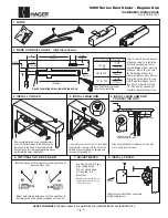

12"
(305mm)
Top of
Frame
A
3/4"
(19mm)
1/2"
(13mm)
1-7/8"
(48mm)
1-3/4"
(44mm)
5-1/2"
(140mm)
L
H
R
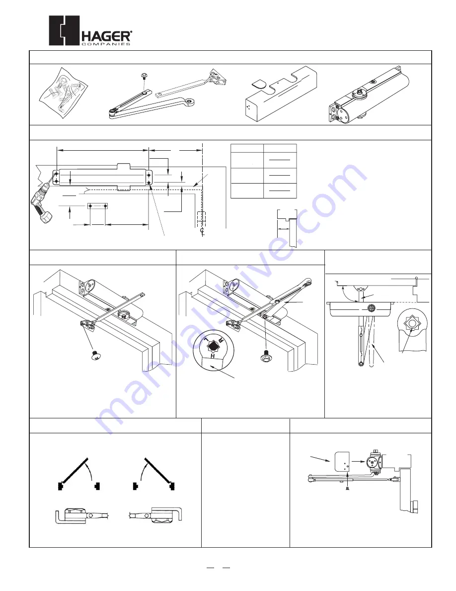
1. PARTS
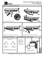
3. INSTALL CLOSER
2. MARK AND DRILL HOLES (
Right Hand Shown)
4. INSTALL MAIN ARM
5. INSTALL MAIN ARM AND
CONNECTING ROD
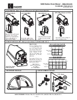
7. ADJUSTMENTS
8. INSTALL COVER
COVER
MAIN ARM
CONNECTING
ROD
MAIN ARM
Select hand of door and the degree of door
opening. Separate template sections “A” and
“B”. Fold template on the corresponding line
for desired degree and hand. Match this line
with the hinge edge of door and attach template
to door. Be sure “Frame” line on template lines
up with the top edge of door. Using a square,
project “Closer Projection Line” on section “A”
of template onto frame and use to align and
attach section “B”. Be sure to align bottom
edge of section “B” with edge of frame. Mark,
prep and drill/tap 1/4"-20 holes for connecting
rod shoe and closer body mounting screws.
Remove template and use mounting screws to
install the closer body to the top jamb and the
connecting rod shoe to the door. Closer body
should be oriented so that the speed regulating
valves are toward the hinge stile of door.
A longer connecting
rod is required for
reveals greater
than 4" (102mm)
Slide cover over closer body and
secure by tightening screws.
Orient main arm so that the “H”, located on the main
arm, lines up with the flat on the spindle. Press arm
down on spindle and secure with spindle bolt.
Slide connecting rod into forearm
of main arm. Rotate main arm until
connecting rod is at a 90˚ angle to
frame. While holding arm in this
position, tighten down forearm screw.
Door Opening
Dimension “A”
To 100
7-1/2"
(191mm)
6"
(152mm)
4-1/2"
(114mm)
101 to 130
131 to *180
*Door/Wall/Hardware/Jamb
conditions permitting
Speed regulating valves toward hinge edge.
5200 Series Door Closer - Top Jamb Arm
Installation Instructions
Meets ANSI A156.4
5
HAGER COMPANIES
139 Victor Street, St. Louis, MO 63104 • (800) 325-9995 • Fax (800) 782-0149
Reveal
FRAME
WHEN ASSEMBLING TO SPINDLE
POSITION OF MAIN ARM
RIGHT HAND DOOR
90
RIGHT
ANGLE
PINION FLAT
See Adjustments on Page 6
for setting Spring Power,
Sweep Speed, Latch Speed,
and Backcheck.
NOTE:
Do not fully unscrew valves or
hydraulic fluid will leak and closer will no
longer be functional.
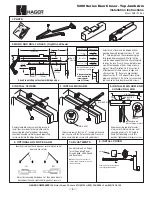
6. OPTIONAL HOLD-OPEN ARM
Identify direction of hold-open nut according to hand of
door and mount arm.
Adjust by loosening hold-open nut, then open door to
desired position and tighten hold-open nut securely.
LH
RH


