6LE007316Ab
Preliminary operations
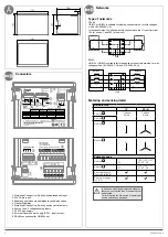
Check the following upon delivery and after removal
of the packaging:
• Packaging and contents are in good condition.
• The product reference corresponds to the order.
• Contents should include:
- 1 ATSE controller
- 1 set of terminals connectors
+ 1 set of door mounting clips
- 1x Quick Start instruction sheet
This Quick Start is intended for personnel trained in
the installation and commissioning of this product.
For further details refer to the product instruction
manual available on www.hager.com.
This product must always be installed and
commissioned by qualified and approved personnel.
Maintenance and servicing operations should be
performed by trained and authorised personnel.
Do not handle any control or power cables connected
to the product when voltage may be, or may become
present on the product, directly through the mains or
indirectly through external circuits.
Always use an appropriate voltage detection device
to confirm the absence of voltage.
Ensure that no metal objects are allowed to fall in the
cabinet (risk of electrical arcing).
Failure to observe good enginering practises as well
as to follow these safety instructions may expose the
user and others to serious injury or death.
Installation and commissioning controller HZI815 / HZI825
Step 1
Installation
Step 2
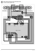
Connection
Step 3
Programming
z
Automatic Transfer Switching
Equipment Controller for HIB4xxM
HZI815 / HZI825
Risk of electrocution, burns or injury to persons
and / or damage to equipment. Risk of damaging
the device In case the product is dropped or
damaged in any way it is recommended to
replace the complete product.
6LE007316Ab
1
6LE007316Ab
5
92
138
1,5 - 3
Clac !
Hager Electro S.A.S., Boulevard d'Europe, B.P. 3, 67215 OBERNAI CEDEX, France - www.hager.com
OCOM 140658
Hager 02.21
6LE007316Ab
6
Trouble shooting guide
Definition
Recommended action
Sources are not detected
- Verify that the product is correctly powered on using the power LED.
- Verify that the DIP switch settings are corresponding to your installation.
Positions are not detected
- Verify that the position input cabling is correctly done.
Source LED are blinking
- Verify that the sources are in the voltage range configured through DIP switch or communication.
- Verify that the sources are cabled correctly.
- Verify that the phase rotation is identical on both sources.
Alarm LED is
blinking
Long blinking
- Verify that Neutral of source I is connected to terminals 103/102 and that Neutral of source II is
connected to terminals 203/202. Connected a Phase instead Neutral can damaged definitely the
product.
- Verify that the input 63A-64A is closed.
- Verify that there has not been a problem during a transfer order and validate fault with the AUTO
button.
Short blinking
- Verify that the DIP switches have not changed position or validate the change of position using the
OK button.
COM LED is on fixed (for HZI825 only)
- Verify that Communication settings are set according to your specification.
- Press “OK” for 30 seconds to reset the Communication settings.
- Contact Hager for other information.
DIP switch parameters are not taken into
account
- Check if the alarm LED is blinking.
- Verify that you are in manual mode when changing DIP switch parameters.
- Press the “OK” button for less than 3s to validate the parameter change.
Interface
Start FT
+ΔU/ΔF
[Hyst]
[Hyst]
-ΔU/ΔF
Vn 230 VAC L/N
Un 400 VAC L/L’
Fn 50 Hz
Start RT
Start FT
Start RT
T
Hysteresis & timers
Settings
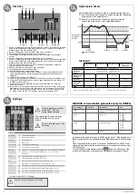
1. Source 1 availability information (Green fixed when source 1 is present and available
and within threshold limits, green blinking when source 1 is present but outside of
threshold limits, off when under 50 VAC).
2. Switch 1 LED position indication (Green fixed when in position 1).
3. Zero position LED indication (Yellow when in position 0).
4. Load supplied information (Green fixed when load is supplied by an available
source).
5. Switch 2 LED position indications (Green fixed when in position 2).
6. Source 2 availability information (Green fixed when source 2 is present and available
and within threshold limits, green blinking when source 2 is present but outside of
threshold limits, off when under 50 VAC).
7. Auto LED indication (Green fixed when in automatic, blinking when transfer is
ongoing, off when in manual mode).
8. Test LED (Yellow fixed when test on load is ongoing).
9. Configurations dip switches (see settings).
10. Run LED (Green when product is powered).
11. Fault LED (Red blinking – long blink when fault or inhibit is activated (63 A - 64 A
open), short blink when a dip switch parameter has been changed and needs
validation).
12. Fire (Red when fire input is activated).
13. COM LED (yellow blinking when RS communications is ongoing) (for HZI825 only).
14. Change AUTO/MANU pushbutton, press at least 3 seconds to switch from AUTO
to MANU or MANU to AUTO.
15. Remote order to switch positions, controller must be in MANU mode for the
buttons to be active.
16. Test button with two functions lamp test and TEST ON LOAD. To start a lamp test
short press on the test button (<3s) ,press again (<3s) to end test. To start a TEST
ON LOAD, long press on the test button (>3s), when LED (8) is blinking press the
“0” button. To end the TEST on load long press on the test button (>3s).
0DT: Dead Band Timer (time to stay in O position during transfer).
FT: Fail Timer (time which the source can be outside the threshold’s
limits before it is considered lost).
RT: Return Timer (time which the source must be within the
threshold’s limits before it is considered available).
Standards
Product must be in manual
mode (LED 7 OFF) for
configuration changes.
After changing DIP switch settings
press OK button shortly (<3s) to
validate.
Cool down timer fixed and set at 180s.
To reset controller: push >30s
OK button.
* hysteresis value is 20% of settings
IEC 60947-6-1*
IEC 61010-2-201 IEC 61010-2-030
GB/T 14048.11
appendix C
Voltage sensing
50-300 VAC L/N 90-520 VAC L/L’
Operating
voltage
184-300 VAC L/N 318-520 VAC L/L’
Measurement
category
CAT III
Frequency
50-60 Hz
50-60 Hz
50-60 Hz
50 Hz
Overvoltage
category
III
III
III
Uimp
4 kV
6 kV**
* When type tested with IEC 60947-6-1 RTSE
** Test level ; Between SOURCES
Source available
DIP switch
1. Network
A
Three phase network
B
Single phase netwrok
2. Prio Set
A
Priority source 1
B
No priority
3. Order mod
A
Control mode impulse logic
B
Control mode contactor logic
4. ΔU/ΔF
A
Setting: +/- 10% of Nominal Voltage and +/- 5% of Nominal Frequency*
B
Setting: +/- 20% of Nominal Voltage and +/- 10% of Nominal
Frequency*
5. 0DT
A
Load supply down time of 2s (0DT = 2s)
B
Load supply down time of 0s (0DT = 0s)
6. FT
A
Wait time of 3s before source is lost (Fail timer = 3s)
B
Wait time of 10s before source is lost (Fail timer = 10s)
7/8. RT
AA
Wait time of 0min (3s) before source returns (returnstimer = 0min (3s))
AB
Wait time of 3min before source returns (returnstimer = 3min)
BA
Wait time of 10min before source returns (returnstimer = 10min)
BB
Wait time of 30min before source returns (returnstimer = 30min)
MODBUS communication parameters (only for HZI825)
Dec. Address
Word count
Description
Unit
40017
1
HZI825 communication node
address
1 … 247
40018
1
Baud rate
2 : 2400
3 : 4800
4 : 9600
5 : 19200
6 : 38400
40019
1
Serial Data format
1 : 8N
2 : 80
3 : 8E
4 : 70
5 : 7E
40020
1
Stop bit
1 … 2
As standard the baud rate is set to 38400, parity bit to 1, Modbus address 3
these parameters can be changed through Modbus using the write function
10.
Once the configuration is done, write data 1 at address Dec. 40565. After
changing the parameters the product buzzer will sound twice and the Com
LED will stay on.
To reset to default parameters press the
button for 30 seconds, the
product will reboot and the standard communication settings will be set.
Technical characteristics
Denomination
Terminal Description
Characteristics
Recommended Cable
section
Tightening torque / screw
type
Control signal outputs (orders
to RTSE)
14
Position II order
AC1 - General use - Ie : 5A, Ue : 250 VAC
DC1 - General use - Ie : 5A, Ue : 30 VDC
1 … 2.5mm²
0.58 Nm
15
Position I order
16
Position 0 order
17
Common point for position output
RS485*
35
NC - Not connected
RS485 isolated bus
LiYCY shielded twisted pair
0.2 Nm / M2
36
Negative electrode
37
Positive electrode
Output for genset
51
Common point
1 … 2.5mm²
0.58 Nm
52
Normaly closed contact
AC1 - General use - Ie : 3A, Ue : 250 VAC
DC1 - General use - Ie : 3A, Ue : 30 VDC
54
Normaly open contact
AC1 - General use - Ie : 5A, Ue : 250 VAC
DC1 - General use - Ie : 5A, Ue : 30 VDC
Controller inhibit input
63A
Controller is inhibited when this contact
is open
Do not use external voltage - Power from
common point
0.5 … 1.5mm²
0.2 Nm / M2
64A
Position inputs (return of
information from RTSE)
70
Common point for position inputs
Do not use external voltage - Power from
common point
0.5 … 1.5mm²
0.2 Nm / M2
71
Position I RTSE
72
Position II RTSE
73
Position 0 RTSE
Fire input
F1
Negative electrode of the 24 VDC
12-24 VDC
0.5 … 1.5mm²
0.2 Nm / M2
F2
Positive electrode of the 24 VDC
Optional Auxiliary supply
24 VDC
81
Negative electrode of the 24 VDC
10-30 VDC (Auxiliary supply for controller,
does not supply RTSE)
1 … 2.5mm²
0.58 Nm / M3
82
Positive electrode of the 24 VDC
Source 1 and 2 voltage inputs
103
Source 1 N
Sensing range:
50-300 VAC L/N
90-520 VAC L/L’
Range:
184-300 VAC L/N
Max consumption: 10 W
1 … 2.5mm²
0.58 Nm / M3
104
Source 1 L1
105
Source 1 L2
106
Source 1 L3
203
Source 2 N
204
Source 2 L1
205
Source 2 L2
206
Source 2 L3
DPS output (RTSE power
supply)
301
Phase output
AC - General use - Ie : 6A, Ue : 250 VAC
DC - General use - Ie : 6A, Ue : 30 VDC
1 … 2.5mm²
0.58 Nm / M3
302
Neutral output
* for HZI825 only


