EQ34 GRADE 1 CYLINDRICAL LOCK
INSTALLATION INSTRUCTIONS
I
-
LS02688
Rev 1, Rev Date: 01/12/2023
[27390107]
Page
3
of
7
Hager Companies 139 Victor Street, St. Louis, MO 63104 (800) 325
-
9995 www.hagerco.com
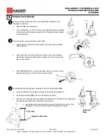
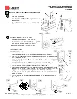
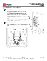
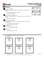
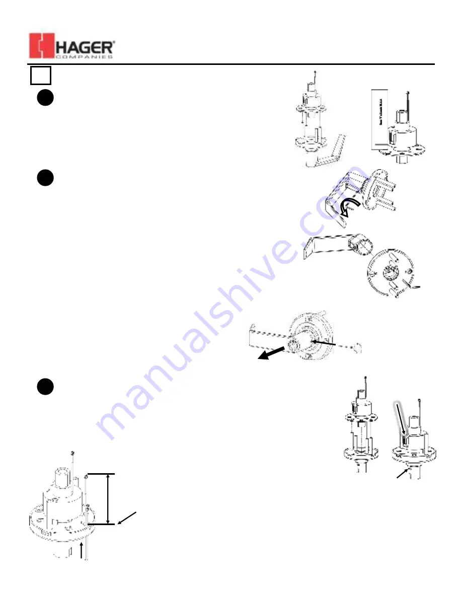
Assemble chassis to spring cage assembly and route wire harness
#19
.
•
Verify the Retractor and Retaining Plate are facing the same direction.
•
Route Wire Harness
#19
(lock to control board) as shown
•
Feed the (2) 2
-
pin plugs through spring cage assembly. In the back of the spring cage,
through the hole behind the retractor as shown below.
•
Adjust harness to line up with the silver line with the face shown. This
should be
3” [76
mm] from the end of the longest 2 pin plug.
4
Remove the lock chassis from the lever assembly and adjust for door
thickness if necessary.
•
Note the thickness of the door.
•
If it is thicker than
1.75” [44.5
mm], then adjust the chassis assembly
to the proper door thickness using the Door Thickness Guide included
with the product.
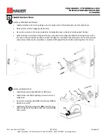
Prepare Lock Chassis
1
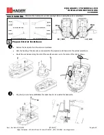
Remove the lever using the Allen wrench,
AA
.
•
Fully loosen set screw in the base of the lever shown below. Rotate
CCW to loosen.
•
Then insert the end of the Allen wrench into a hole in the retaining
plate below and pull back the plate to release the lever. Remove the
lever and set aside.
•
KEY OVERRIDE ONLY! To remove the lever, insert lever removal tool
BB and pull the lever off. Set the lever aside for later.
2
3
Retaining
Plate
Retractor
Align line with plate
3” [76
mm]


