background image

EQ34 GRADE 1 CYLINDRICAL LOCK


INSTALLATION INSTRUCTIONS


I

-

LS02688


Rev 1, Rev Date: 01/12/2023


[27390107]


 Page 

8

 of 

7


Hager Companies  139 Victor Street, St. Louis, MO 63104   (800) 325

-

9995   www.hagerco.com


7

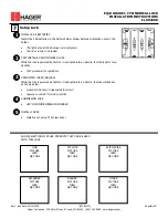
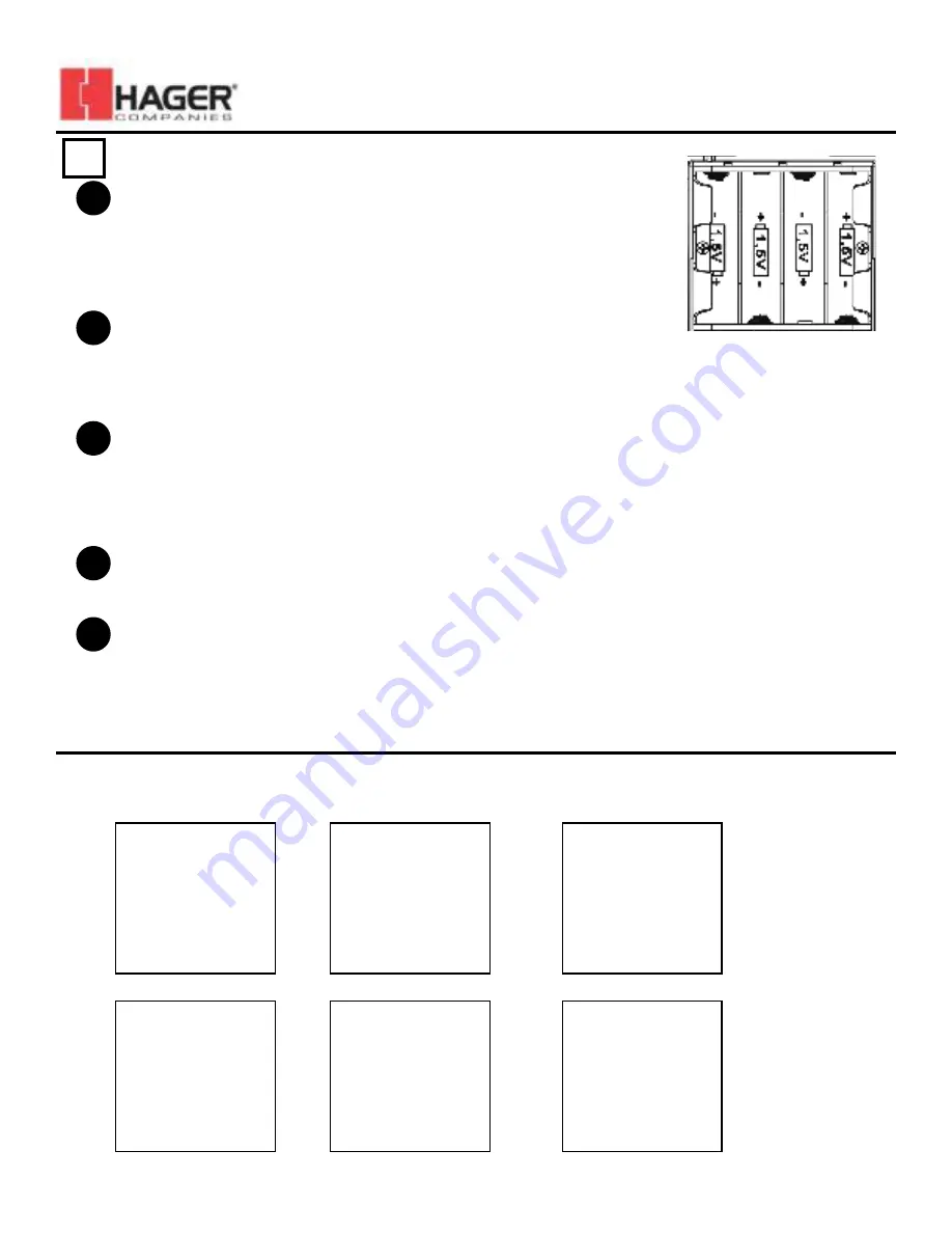
INSTALL 4 AA BATTERIES


Install the 4 AA batteries in the battery holder. Follow batterie orientation notes in the 

holder.


• 

The lights should blink between red and green


• 

It is now  ready to be tested. 


Setup Lock


1


UNADOPTED LOCKS (ORPHAN)


While the lock is powered but before it is adopted into a network, the lock will behave 

as shown below.


• 

Locked all the time? Unlocked all the time?


• 

Anyway to unlock? Provide a card for 


3


COMMISSION LOCK


• 

GO TO COMMISSIONING PROCEDURE 


4


SHOW SELECTION OF OTHER PRODUCTS THAT CAN BE USED 

WITH THIS LOCK


HUB


PICTURE


INFO 


QR CODE


CYL LOCK


PICTURE


INFO 


QR CODE


EXIT DEVICE


PICTURE


INFO 


QR CODE


EXTENDER


PICTURE


INFO 


QR CODE


READER


PICTURE


INFO 


QR CODE


OTHER


PICTURE


INFO 


QR CODE


TEST INSTALLED AND POWERED LOCK


While the lock is powered but before it is adopted into a network, test the lock for func-

tionality. 


• 

Test procedure for cylindrical


2


INSTALL COVER


• 

Install cover, using T10 screw driver


5


Summary of Contents for I-LS02688

Page 1: ...llen Wrench 3 32 1 BB Lever Removal Tool 1 CC Screw 10 32 x 1 4 Oval Head Machine 4 DD Screw 12 24 X 3 4 Flat Head Combo 2 EE Screw 8 32 x 3 4 Flat Head Combo 2 12 Set Screw 10 32 x 1 4 3 32 Drive 2 1...

Page 2: ...ip the prep steps if the door has already been prepared Just install the latch and strike as shown below 1 NOTE Drill from both sides to avoid splintering the finished surface of wood doors Distance f...

Page 3: ...6 mm from the end of the longest 2 pin plug 4 Remove the lock chassis from the lever assembly and adjust for door thickness if necessary Note the thickness of the door If it is thicker than 1 75 44 5...

Page 4: ...he exterior escutcheon Route the wire harness along the side of the escutcheon and over to the center of the lock as shown Prepare Exterior Escutcheon 1 INSIDE OUTSIDE INSIDE OUTSIDE INSIDE OUTSIDE IN...

Page 5: ...e unit box into the exterior spindle as shown 2 Install tailpiece 21 included in unit box on the KIK cylinder purchased separately inline with the pin bible as shown 3 Loosen set screw 12 in lever 8 w...

Page 6: ...escutcheon flat against the door plug interior mounting plate 5 into wiring harness and stow the wires in the area behind the chassis Position the plate over the chassis and fasten down with 2 CC scr...

Page 7: ...driver Position the power pack base onto the door aligning the upper mounting holes and routing the wires through the bottom wiring hole While holding the pack install 2 12 screws FF into the pre par...

Page 8: ...before it is adopted into a network the lock will behave as shown below Locked all the time Unlocked all the time Anyway to unlock Provide a card for 3 COMMISSION LOCK GO TO COMMISSIONING PROCEDURE 4...

Page 9: ...tlet on a circuit different from that to which the receiver is connected Consult the dealer or an experienced radio TV technician for help Changes or modifications to the device not expressly approved...

Reviews: