IV.
OPERATING SYSTEMS
24
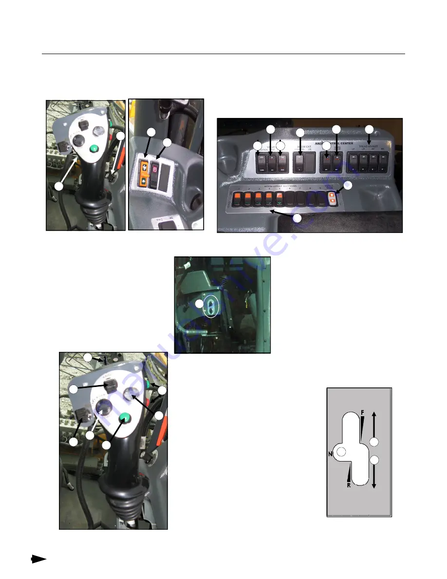
A. CAB
Side Console
FIG. 24-6
A. Hydrostatic Lever
B. Speed Control
C. Throttle switch
D. Brake/Ladder switch
E. Agitation switch
F. Solution Tank switch
G. Rinse Tank switch
H. Boom Extension switch
I.
Float switch
J. Work Mode switch
K. Tread Adjust switches
L. Boom Spray Section switches
M. Fence Row Nozzle switch
N. Power Ports
FIG. 24-1
A
B
C
D
O. Forward
P. Neutral/Stop
Q. Reverse
R. Foamer switch
S. Hydraulic Lift
T. Left Boom (level, horizontal fold)
U. Right Boom (level, horizontal fold)
V. Master switch “ON”
W.
Speed Range switch
X. All Up/Hold switch
R
S
T
U
V
W
N
FIG. 24-4
FIG. 24-5
O
P
Q
FIG. 24-3
E
F
G
H
I
J
K
M
L
OPERATING SYSTEMS
X
FIG. 24-2


