7-33
SECTION 7 –
SPRAY SYSTEMS
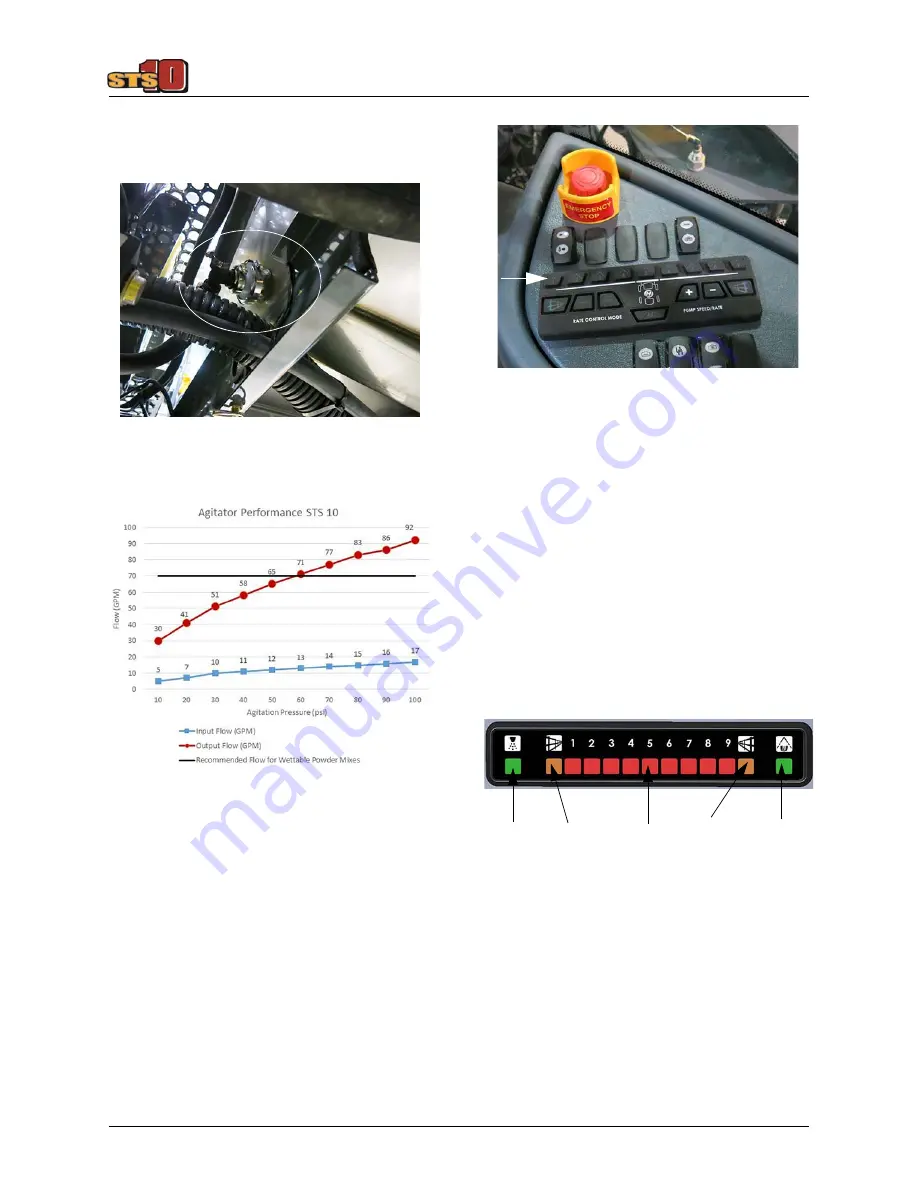
the end of each Jet Agitator (inside of the
solution tank) and provide ample agitation
and solution suspension.
Boom Solution Valve Switches
The spray booms are divided into sections
that are independently supplied with solution
and can be turned on or off individually. The
electrically-operated boom solution valves
are controlled by the Boom Solution Valve
Switches (located on the side console).
•
Press the Boom Solution Valve Switches
to turn ON. Press again to turn OFF.
NOTE: Each Boom Solution Valve Switch is
equipped with an indicator light and
will illuminate when the
corresponding Boom Solution Valve
is OFF.
Section Indicator Display
The Section Indicator Display (located on
the cab headliner) allows you to view system
status for the following:
•
(1) - Master Spray Indicator (illuminates
when ON).
•
(2) - Fence Row Indicators (illuminate
when ON).
•
(9) - Spray Section Indicators (illuminate
when OFF).
•
(1) - Rear Wheel Nozzle Indicator (illumi-
nates when ON).
Jet Agitator
(Located on each end of the solution tank)
-Typical View
Boom Solution Valve Switches
(Located on the side console)
-Typical View
Section Indicator Display
(Located on the cab headliner)
-Typical View
• Master
Spray
• Right
Fence
Row
• Rear
Wheel
Nozzle
• Spray
Section
• Left
Fence
Row
Summary of Contents for STS 10
Page 290: ......


