SECTION 7 –
SPRAY SYSTEMS
7-44
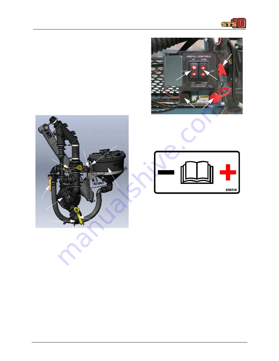
Inductor Assembly Components
•
(A) - Side Fill Valve
•
(B) - Rinse Supply Valve
•
(C) - Chemical Inductor Valve
•
(D) - Transfer Pump
•
(E) - Swirl Valve
•
(F) - Chemical Inductor Tank
•
(G) - Fill Port
•
(H) - Fill Valve
•
(I) - Pump Speed Switch
•
(J) - Raise/Lower Switch
•
(K) - Pump Activation Lever
•
(L) - Power Ports
NOTE: Two power ports (L) are provided for
chemical pump connection.
1. Engage the parking brake.
2. Start the engine.
3. Lift the Pump Activation Lever (K) UP.
4. Lower the Inductor Assembly by press-
ing the Raise/Lower Switch (J) in the
DOWN (Lower) position.
5. Press the Pump Speed Switch (I) in the
UP (On) position ONCE to activate the
Transfer Pump.
6. Press and hold the Pump Speed Switch
UP to increase speed or DOWN to
decrease speed.
NOTE: Engine speed automatically
increases to 1500 RPM at maximum
pump speed.
NOTE: Always match pump speed to
available supply to avoid pump
damage.
NOTE: Whether filling with the Transfer
Pump or an off-site pump, ensure the
Transfer Pump is running.
Inductor Assembly
-Typical View
A
B
C
D
F
G
H
E
Side Fill Control Panel
-Typical View
L
K
I
J
Summary of Contents for STS 10
Page 290: ......


