FIG. 4.9D-1
4.9D
OPERATING SYSTEMS CONTINUED
IV.
OPERATING SYSTEMS
D. SPRAY SYSTEMS
RINSE SYSTEM OPERATION–
Activate the system only after solution tank is empty. Select a safe
area to rinse spray system and clean sprayer where the chemicals will not drift off to contaminate people, ani-
mals, vegetation, or water supply. Refer to chemical manufacturer’s guide for types of cleaning solution com-
binations (plain water, cleaning agents, etc. ).
TO RINSE SOLUTION TANK AND 3” FILL LINES:
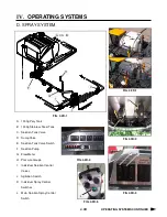
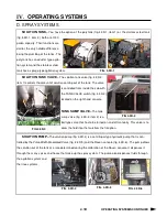
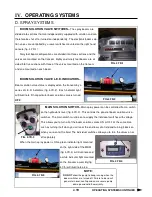
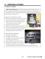
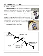
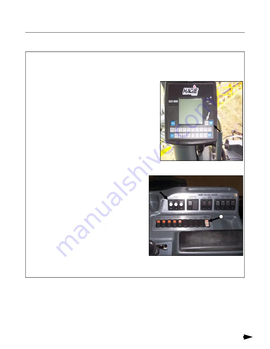
The solution pump is controlled by the Raven console (fig. 4.9D-1)
1. Turn on spray system console. Turn the rate switch to the
MANUAL position. Using the flow increase/decrease lever, in-
crease the solution pressure to maximum PSI.
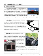
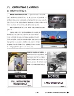
2. Close the solution tank valve (fig. 4.9D-2).
3. Depress the “SOLU TANK” rinse switch (fig. 4.9D-2, item 3).
4. When finished rinsing the solution tank, return the rinse switch
back to the OFF position and turn the spray system OFF
(including the solution pump switch, and console).
TO RINSE BOOM SUPPLY AND NOZZLES:
1. Follow steps 1 and 2 from above.
2. Turn agitation OFF (fig. 4.9D-2, item 1).
3. Close solution tank valve (fig. 4.9D-2, item 2) and open
boom supply valves (fig. 4.9D-2, item 4).
4. Depress the “BOOM” rinse switch (fig. 4.9D-2, item 3).
5. When finished rinsing the boom, return the rinse switch
back to the OFF position and turn the spray system OFF
(including the solution pump switch, console, boom solution valves, and main spray power switch)
1 2 3
FIG 4.9D-2
4
Auto
/Man.
Solution
pump
ON/OFF
switch
Summary of Contents for STS 10
Page 119: ...9 9 IX TROUBLE SHOOTING NOTES...
Page 127: ...NOTES NOTES...

