


7-14
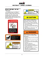
SECTION 7 –
SPRAY SYSTEMS
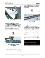
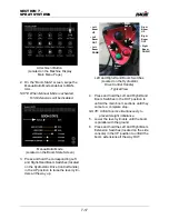
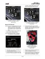
Main Breakaway
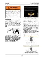
To Reset the Main Breakaway
•
Once the boom has broken away, press
the corresponding Left or Right-Hand
Boom Switch (located on the Hydrostatic
Drive Control Handle) in the OUT posi-
tion momentarily to stop movement and
reset the hydraulic breakaway function
valve (located on center of transom).
NOTE: The hydraulic breakaway function
breaks between 3500-4350 psi (241-
299 bar).
•
Press and hold the corresponding Left or
Right-Hand Boom Switch in the OUT
position until the main fold section has
resumed spray position.
NOTE: The main boom breakaways cannot
be folded unless machine speed is
less than 5 mph (8 km/h).
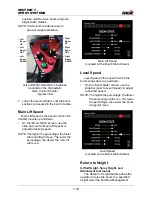
Outer Breakaway
The Outer Breakaway is self-resetting and
will return to the normal operating position
after it has cleared the hazard.
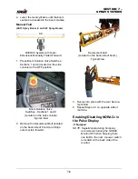
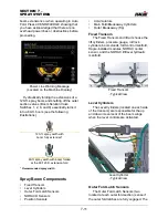
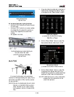
Adjusting Breakaway Tension
NOTE: Recommended tension for the spring
breakaway is approximately 17”/43.2
cm (distance from the first coil to the
last coil, as shown in the following
illustration). Settings below 17”/43.2
cm could result in breakaway hinge
damage due to excessive movement
during field operation. If the
breakaway springs are set to 17”/
43.2 cm (3.5”/8.9 cm of stretch from
resting state), exerted force by the
springs is 1,100 lbs./499 kg.
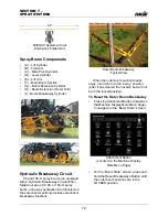
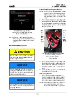
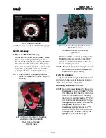
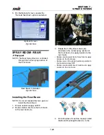
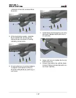
Boom Charge Indicator
(Located along the top of each display page)
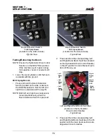
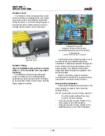
Left and Right-Hand Boom Switches
(Located on the Hydrostatic
Drive Control Handle)
-Typical View
• Right
Boom
OUT
• Left
Boom
OUT
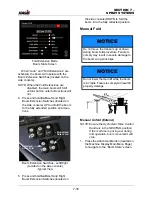
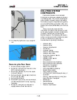
Hydraulic Breakaway Function Valve
- Main Breakaway
(Located on center of transom)
-Typical View
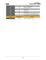
Summary of Contents for STS/DPS Series
Page 2: ...5 DASH AUTO...
Page 5: ...Troubleshooting 10 38...
Page 52: ...SECTION 2 SAFETY AND PRECAUTIONS 2 15 650210 Located on each NORAC sensor...
Page 380: ...NOTES 5 DASH AUTO...
Page 381: ...NOTES 5 DASH AUTO...
Page 382: ...NOTES 5 DASH AUTO...


