background image

7-38

SECTION 7 –

SPRAY SYSTEMS

Visit 

www.teejet.com

 for further 

information.

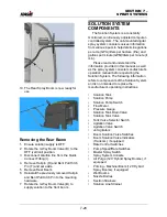
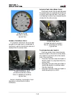
Section Strainers

(80-Mesh Strainer Screens)

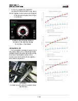
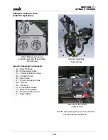
Two (2) Section Strainers are located on 

the transom and filter impurities to aid in the 
avoidance of spray nozzle buildup.

Refer to “Service - Filters” provided in the 

Maintenance and Storage Section

 elsewhere 

in this manual for maintenance information.

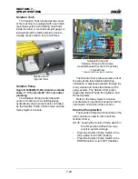
Solution Line Strainer

(50-Mesh Strainer Screen)

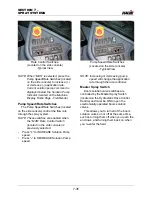
A Solution Line Strainer is located 

beneath the center right-hand side of 
machine and is the main strainer to filter 
solution system impurities and maintain 
consistent application rates.

Refer to “Service - Filters” provided in the 

Maintenance and Storage Section

 elsewhere 

in this manual for maintenance information.

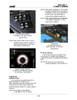
SOLUTION SYSTEM - 
OPERATION

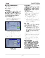
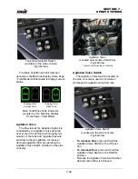
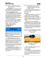
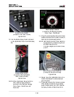
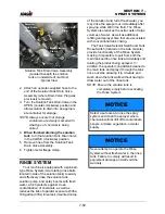
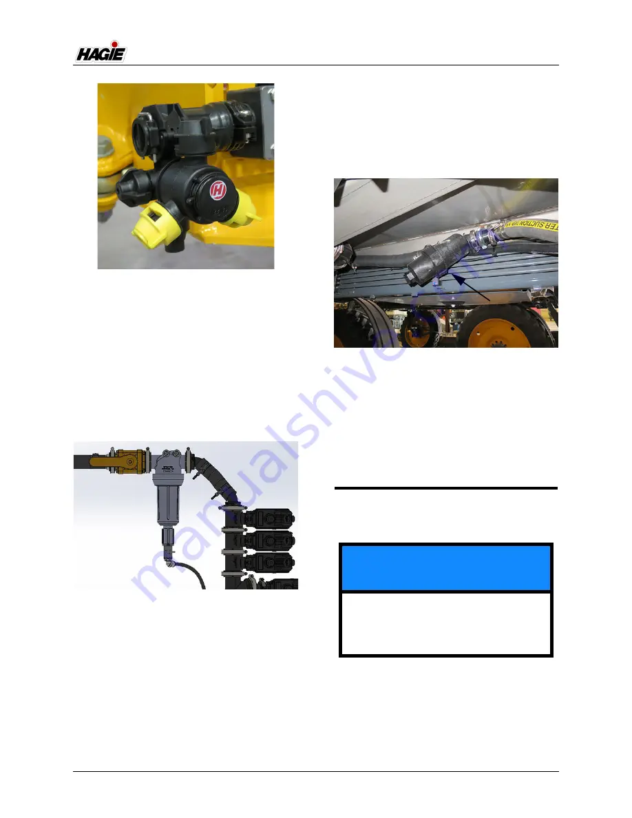
Nozzle Body

(Located throughout boom)

-Typical View

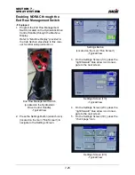
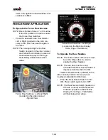
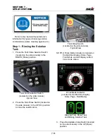
Section Strainer (2)

(Located on transom)

-Typical View

NOTICE

The Solution System has been tested 
using RV-type antifreeze. Fill solution 
tank with fresh water and drain before 
initial use.

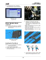
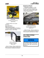
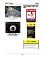
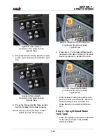
Solution Line Strainer

(Located beneath the center

right-hand side of machine)

-Typical View

Summary of Contents for STS/DPS Series

Page 1: ...9 STS DPS OPERATOR S MANUAL 493774 CALIFORNIA Proposition 65 Warning Diesel engine exhaust and some of its constituents are known to the State of California to cause cancer birth defects and other rep...

Page 2: ...5 DASH AUTO...

Page 3: ...ns 1 7 Torque Values 1 22 2 SAFETY AND PRECAUTIONS Intended Use 2 1 Safety Precautions 2 1 Seat Belt 2 7 Rotating Beacon 2 7 Emergency Stop 2 8 Emergency Exit 2 8 Fire Extinguisher 2 9 Safety Decals 2...

Page 4: ...ution System Operation Dual Product 8 13 Rinse System Dual Product 8 18 Filling Your Solution Tank Dual Product 8 31 Draining Your Solution Tank Dual Product 8 35 Application Dual Product 8 37 9 MAINT...

Page 5: ...Troubleshooting 10 38...

Page 6: ...ual will aid you in the proper operation and service of your machine It is the responsibility of the user to read the operator s manual and comply with the correct and safe operating procedures as wel...

Page 7: ...and gear ratio To ensure prompt efficient service when ordering parts or requesting service repairs record the serial numbers and identification numbers in the following spaces provided Machine The ma...

Page 8: ...on the rear left hand frame open hood to access STS14 STS16 The engine has an identification plate located on the right hand side above batteries that provides engine serial number as well as other ma...

Page 9: ...information Refer to your Parts Manual for specific part number Wheel Motors The wheel motors each have an identification plate mounted on the side of motor that provides motor serial number as well...

Page 10: ...plate mounted on the lower right hand side of transom that provides boom model and serial number Wheel Motor Identification Plates Typical View _______________________ Right Front ____________________...

Page 11: ...N Steel Spray Booms 90 100 Hybrid Spray Booms 120 90 100 Steel Spray Boom Identification Plate Typical View Serial No _______________________ 120 Hybrid Boom Identification Plate Typical View Serial N...

Page 12: ...UCTION 1 7 SPECIFICATIONS Machine Dimensions NOTE Dimensions on your machine may vary depending on tire size Your machine may vary depending on boom option Illustration 1a B C3 C1 C2 F Illustration 1b...

Page 13: ...m 87 110 23 221 cm 279 4 58 4 cm D Static Loaded Hub Height 38 3 8 97 5 cm 38 3 8 97 5 cm 38 3 8 97 5 cm E Wheel Base STS10 STS12 140 355 6 cm STS14 STS16 166 421 6 cm STS10 STS12 140 355 6 cm STS14 S...

Page 14: ...s 13 138 kg with 90 steel boom 28 966 lbs 13 138 kg with 100 steel boom 29 006 lbs 13 156 kg with 120 hybrid boom STS14 24 926 lbs 11 306 kg machine only 29 046 lbs 13 175 kg with 90 steel boom 29 046...

Page 15: ...ion A Wheel Base STS10 STS12 140 355 6 cm STS14 STS16 166 421 6 cm B Static Loaded Hub Height 38 3 8 97 5 cm C Overall Sprayer Height from middle of GPS unit 156 4 397 3 cm D Length from front of boom...

Page 16: ...lowing spaces provided when programming your spray system console Refer to this information for future reference Record calculated calibration values in the spaces provided below Speed Cal Section Wid...

Page 17: ...in3 Horse Power STS10 280 hp 209 kW 2400 rpm 300 hp 224 kW 2400 rpm peak power STS12 300 hp 224 kW 2400 rpm 300 hp 224 kW 2400 rpm peak power STS14 300 hp 223 kW 2200 rpm 333 hp 248 kW 2000 rpm peak...

Page 18: ...normal field conditions Turning Radius NOTE May vary depending on tire size STS10 STS12 25 ft 7 5 m No AWS AWS Off 18 ft 5 5 m AWS On if equipped STS14 STS16 27 ft 8 m No AWS AWS Off 20 ft 6 m AWS On...

Page 19: ...der optional John Deere optional Fence Row Nozzle Remote Activated left and right Rear Nozzle Remote Activated Solution Circuit Pressure Maximum 100 PSI 6 9 bar Modular Injection System if equipped Ch...

Page 20: ...min Boom Solution Valves 2 Ball Valves Electric Actuation Stainless Ball Stem PTFE Seats Pressure Gauge 2 160 PSI 11 bar Glycerin Filled Console Raven optional Ag Leader optional John Deere 2630 opti...

Page 21: ...Dome Light Tinted Glass Instructor Seat Temperature Control Full Range A C Charge Type R 134A Fresh Air Filtration RESPA Cab Filter Charcoal Filter Seat Air Ride Instruments Tachometer RPM Fuel Level...

Page 22: ...diator and surge tank STS10 STS12 11 7 gallons 44 2L John Deere Cool Gard II STS14 STS16 11 gallons 41L John Deere Cool Gard II Diesel Exhaust Fluid DEF Tank Final Tier 4 Engines 7 8 gallons 29 5L Joh...

Page 23: ...irestone Radial All Trac RC 179D 70 16 2 17 100 80 7 37 3 244 0 327 LSW680 55R42 Goodyear LSW 171D 29 27 1 13 600 71 5 32 9 218 4 523 7 380 90R46 Goodyear Ultra Sprayer 168A8 B 78 14 4 12 300 72 6 32...

Page 24: ...Trac RC 179D 4 4 41 1 7 773 205 0 94 7 619 8 2110 0 LSW680 55R42 Goodyear LSW 171D 2 0 68 9 6 168 181 5 83 5 554 7 3378 7 380 90R46 Goodyear Ultra Sprayer 168A8 B 5 4 36 6 5 579 184 4 82 8 551 2 1787...

Page 25: ...540 5200 6000 6800 7600 8250 8550 9100 VF380 90R46 Michelin N A N A N A N A N A N A N A N A N A VF420 95R50 Michelin N A N A N A N A N A N A N A 11350 11830 620 70R38 Michelin N A N A N A 7390 7910 N...

Page 26: ...0 Goodyear N A 2059 2358 2721 3084 3447 3742 3878 4127 VF380 90R46 Michelin N A N A N A N A N A N A N A N A N A VF420 95R50 Michelin N A N A N A N A N A N A N A 5148 5366 620 70R38 Michelin N A N A N...

Page 27: ...1 or 5 2 SAE Grade 8 or 8 2 Lubricatedb Dryc Lubricatedb Dryc Lubricatedb Dryc Lubricatedb Dryc N m lb in N m lb in N m lb in N m lb in N m lb in N m lb in N m lb in N m lb in 1 4 3 7 33 4 7 42 6 53...

Page 28: ...cateda Dryb Lubricateda Dryb N m lb in N m lb in N m lb in N m lb in N m lb in N m lb in N m lb in N m lb in M6 4 7 42 6 53 8 9 79 11 3 100 13 115 16 5 146 15 5 137 19 5 172 N m lb ft N m lb ft N m lb...

Page 29: ...and or defects 2 Inspect the O ring It must be free of damage and or defects 3 Lubricate O rings using system oil and install into groove 4 Push O ring into groove so O ring is not displaced during a...

Page 30: ...d Size Straight Hex SizeB Adj Lock Nut Hex Size Steel or Gray Iron Torque Aluminum or Brass TorqueC mm Dash Size in mm in mm N m lb ft mm N m lb ft mm mm mm N m lb ft N m lb ft 4 2 0 1 25 3 18 M8x1 12...

Page 31: ...9 51 46 34 20 12 0 7 50 19 0 5 1 3 16 12 36 102 75 41 175 129 M27x2 32 32 10 0 74 67 49 22 14 0 8 75 22 2 3 1 3 16 12 36 102 75 41 175 129 M30x2 36 36 13 0 96 87 64 25 16 1 0 00 25 4 0 1 7 16 12 41 14...

Page 32: ...ht Hex SizeB Adj Lock Nut Hex Size Steel or Gray Iron Torque mm Dash Size in mm in mm N m lb ft mm N m lb ft mm mm mm N m lb ft 4 2 0 12 5 3 18 M8x1 12 12 8 6 5 3 0 18 8 4 76 M10x1 14 14 15 11 6 4 0 2...

Page 33: ...5 8 5 8 16 1 2 11 8 8 5 0 312 7 92 1 2 20 3 4 11 16 24 1 8 16 1 2 10 6 0 375 9 53 11 16 16 13 16 37 27 1 42 31 9 16 18 3 4 3 4 37 2 7 25 1 8 12 8 0 500 12 70 13 16 16 15 16 50 37 1 1 8 93 69 3 4 16 7...

Page 34: ...ze Jam Nut Torque Thread Size Straight Hex SizeB Adj Lock Nut Hex Size Steel or Gray Iron Torque mm Dash Size in mm in in N m lb ft N m lb ft in in in N m lb ft 5 3 0 18 8 4 78 3 8 24 5 8 9 16 18 13 6...

Page 35: ...e in the center of the flange and install four cap screws With the flange centrally located on the port hand tighten cap screws to hold it in place Do not pinch O ring 5 For both single piece flange a...

Page 36: ...47 85 35 63 1 1 2 1 2 13 UNC 62 131 46 97 2 1 2 13 UNC 73 131 54 97 2 1 2 1 2 13 UNC 107 131 79 97 3 5 8 11 UNC 187 264 138 195 3 1 2 5 8 11 UNC 158 264 117 195 4 5 8 11 UNC 158 264 117 195 5 5 8 11...

Page 37: ...1 17 N m 150 lb in M12 x 1 5 28 N m 20 6 lb in M14 x 1 5 39 N m 28 7 lb in M16 x 1 5 48 N m 35 4 lb in M18 x 1 5 60 N m 44 2 lb in M20 x 1 5 60 N m 44 2 lb in M22 x 1 5 85 N m 62 7 lb in M27 x 2 135...

Page 38: ...per use of the sprayer its attachment or any sprayer equipment Do not make any modifications such as but not limited to weldments add ons adaptations or changes from the original design of the sprayer...

Page 39: ...under any overhead obstructions Contact with power lines may result in serious injury or death Booms must be folded and in cradles when driving the machine on a roadway or when near power lines Remove...

Page 40: ...radar beam as itemits a very low intensity microwave signal which may result in possible eye damage Handle Fuel Safely Always turn the engine off and allow it to cool before refueling NEVER smoke whil...

Page 41: ...ad compounds chemicals known to the State of California to cause cancer and reproductive harm Wash hands after handling Avoid serious injury by avoiding battery acid contact with your body Battery ele...

Page 42: ...pose of empty chemical containers properly Wash spilled chemicals or spray residue from the sprayer to prevent corrosion and deterioration Select safe areas to fill flush calibrate and clean the spray...

Page 43: ...perature is less than 50 F the operator may experience control loss on the 90 ft and 100 ft fold cylinders These cylinders are the main cylinders affected by over running loads due to the weight rotat...

Page 44: ...before reversing directions Always drive at a reasonable field speed Add On Equipment Add on equipment may cause unstable conditions when lifting machine or detaching the spray boom Remove all add on...

Page 45: ...d on the face of the button When the E Stop Switch is activated a warning message will appear on the Machine Display to alert the operator that the E Stop is engaged Press OK to acknowledge EMERGENCY...

Page 46: ...Fire Extinguisher is required follow the manufacturer s operating instructions provided on the Fire Extinguisher To Remove Fire Extinguisher Pull the Security Latch OUTWARD to disengage and remove Fi...

Page 47: ...hine striping may be purchased through your local John Deere dealer To replace safety decals ensure the installation area is clean and dry and decide on exact position before you remove the backing pa...

Page 48: ...near each lifting point containment ring 650516 1 Located near front fill 1 Located near side fill 650517 Located near battery disconnect switch RISK OF INJURY DUE TO IMPROPER LIFTING DO NOT ATTEMPT T...

Page 49: ...e HXE28534 Located on front left hand cross member near quick connect multi coupler 650637 Located on right hand cross member beneath cab N404969 1 Located near main air tank 1 Located near air purge...

Page 50: ...r air purge air tank if equipped N401323 Located near the fuel fill ladder 650431 Located near fuel fill Final Tier 4 engines only T188283 Located near reversible fan N204628 Located on front left han...

Page 51: ...ar solution tank lid 1 Located near Dual Product solution tank lid if equipped N203265 1 Located near solution tank lid 1 Located near Dual Product solution tank lid if equipped 1 Located on side fill...

Page 52: ...SECTION 2 SAFETY AND PRECAUTIONS 2 15 650210 Located on each NORAC sensor...

Page 53: ...ntaining desired armrest posi tion re tighten bolts Armrest Tilt Dial B Tilts armrests Roll Armrest Tilt Dial located on side of operator s seat INWARD towards oper ator to tilt armrest DOWN Roll Armr...

Page 54: ...bar Knob OUTWARD away from operator for decreased curve Document Pouch K Storage for various machine manuals Pull Document Pouch Fastener to OPEN Push Document Pouch Fastener to CLOSE Seat Belt Refer...

Page 55: ...rotate down 20 degrees Third Position hold and rotate down 30 degrees Hold and rotate down to return Headrest to 0 degree posi tion Heat Cool Selector Switch B Selects between heat and cool settings...

Page 56: ...ter J Adjusts armrest height Loosen two 2 bolts and move armrests up or down While maintaining desired armrest posi tion re tighten bolts Fore Aft Lockout Isolator K Locks or unlocks fore aft isolatio...

Page 57: ...t Console A Hazard Warning Lights Switch B Highway Running Lights Switch C Steering Wheel D Turn Signal Indicator Left E Highway Running Lights Indicator F High Beams Indicator G Turn Signal Indicator...

Page 58: ...achine s drive state must be in Road Mode to activate the Hazard Warning Lights NOTE The Hazard Warning Lights are tied to battery power and will operate when the machine is off The flashers are disab...

Page 59: ...further information Highway Running Lights Switch Headlights The Highway Running Lights located on the front and rear of machine are to be used when traveling on a public roadway at night NOTE The Hi...

Page 60: ...ted on the right hand side of the steering column UP to loosen enough to freely move the steering wheel With the handle loosened adjust steer ing wheel to desired position While hold ing the wheel in...

Page 61: ...and entering the cab With your foot on the Steering Column Release Pedal located on the lower left hand side of the steering column push pedal DOWN and move the steering col umn to desired position To...

Page 62: ...ng Decel Pedal minimum speed Horn The Horn is sounded by pressing the Horn Button located on the end of the turn signal lever INWARD Windshield Washer The Windshield Washer Button is located on the en...

Page 63: ...ng column mounted and Machine Display indicator lights will flash correspondingly when either turn signal is activated High Beams Brights To turn the High Beams ON push the turn signal lever located o...

Page 64: ...Q Transom Switch Up Down R Left Hand Boom Switch S Right Hand Boom Switch T Master Spray Switch U End Row Management Switch V Shift Up Switch W Shift Down Switch X Parking Brake Switch Y Throttle Swi...

Page 65: ...he Safety and Precautions Section elsewhere in this manual for further information Foam Marker Switch If Equipped The Foam Marker Switch located on the side console controls foam application on both s...

Page 66: ...Spray Switch located on the Hydrostatic Drive Control Handle Refer to Rinse System provided in the Spray Systems Section elsewhere in this manual for further information Boom Solution Valve Switches...

Page 67: ...behind the rear tires Refer to the Spray Systems Section elsewhere in this manual for further information Rate Control Switches The Rate Control Switches located on the side console control the rate i...

Page 68: ...re in this manual for further information Tank Valve Selector Switch The Tank Valve Selector Switch located on the side console is a three position switch that allows the operator to pull from either...

Page 69: ...Boom Extension Switches 1 left and 2 right to unfold fold the outer boom extensions separately WARNING When operating or positioning the booms observe the following safety precautions to avoid serious...

Page 70: ...system Power Mirrors If Equipped Your machine may be equipped with Power Mirrors for your operating convenience Press the L R Lever in the L position to adjust the LEFT mirror or in the R posi tion to...

Page 71: ...he boom solution valves End Row Management Switch The End Row Management Switch located on the Hydrostatic Drive Control Handle is a programmable switch that enables various functions i e All Wheel St...

Page 72: ...speed RPM A Hydrostatic Drive Control Handle B Right Hand Boom IN C Right Hand Boom UP D Right Hand Boom OUT E Right Hand Boom DOWN F Left Hand Boom OUT G Left Hand Boom UP H Left Hand Boom IN I Left...

Page 73: ...ng the lower left hand side of operator s seat are provided for the connection of additional items such as radios and computer equipment NOTE The Power Ports are not intended for the permanent connect...

Page 74: ...SECTION 3 CAB 3 22 Typical View B Typical View Standard Optional C Typical View D Typical View Your machine may vary depending on model and available equipment E Typical View F...

Page 75: ...manual for complete operating instructions and programming information Climate Controls Standard Fan Blower Speed A Rotate the Fan Blower Speed Dial clockwise to increase fan speed Rotate the Fan Blo...

Page 76: ...aintain the set point temperature When active A C function is disabled Press the Econ Switch to turn ON Press the Econ Switch again to return the system back to normal operation NOTE An indicator ligh...

Page 77: ...e operating instructions Machine Display The Machine Display in your sprayer is the central control center of the machine It controls many of the machine s electronically driven functions e g machine...

Page 78: ...hine Display provided elsewhere in this section for operating instructions Work Lights The Work Lights located on each boom cradle are for use when operating in the field after dark and are turned on...

Page 79: ...the spray pattern NOTE The Battery Disconnect Switch located inside the engine compartment on the rear right hand side of machine open hood to access must be in the ON position to activate the Night...

Page 80: ...lter located behind the exterior service panel on the right hand side of cab which eliminates hazardous chemicals from the operator s station In addition a Recirculation Filter accessible after the Ch...

Page 81: ...ny of the machine s electronically driven functions such as Machine Drive All Wheel Steer if equipped Hydraulic Tread Adjustment if equipped Attachment Operation Spray Systems Reversible Fan Rear View...

Page 82: ...ermine what kind of work it is meant to do field work or transport work Road Mode In Road Mode the machine is limited on what functions can be operated Road Mode is used for transporting the machine a...

Page 83: ...ed NOTE Press the center of the Speedometer to navigate to the Speed Settings screen NOTE See Main Menu for information on changing the unit of measure Target Speed NOTE Machine speed is limited to 20...

Page 84: ...xhaust Temperature HEST Low Hydraulic Oil Level Low Engine Oil Pressure Low Engine Coolant Level Insufficient Cab Air Pressure Low Diesel Exhaust Fluid DEF Final Tier 4 Engines Engine Emissions System...

Page 85: ...quipped with a Rear View Camera for your safety and convenience when operating the machine in reverse and is integrated into the rear hood Press the Camera Button located on the Home Page Road Mode to...

Page 86: ...er Spray Indicator When the Master Spray Switch located on the Hydrostatic Drive Control Handle has been activated a Master Spray Indicator located on the Home Page Field Mode will illuminate Fence Ro...

Page 87: ...ions are not met the AWS Button will remain ON but the AWS indicator will turn OFF and the machine will be operating in conventional steering mode When conditions are met again AWS will automatically...

Page 88: ...eld Mode to navigate to the Main Menu Page NOTE You may also press the Main Menu Button located on the bottom right hand corner of each display page to navigate directly to the Main Menu Page Home Pre...

Page 89: ...Lights Button ATCH1 to turn Attachment Lights ON Press button again to turn Attachment Lights OFF NOTE Turn the Attachment Lights OFF before entering a public roadway NOTE The ignition key must be in...

Page 90: ...ction and select ALL LIGHTS or TOGGLE 2 SETTINGS All Lights When ALL LIGHTS is selected Field Lights Work Lights Attachment Lights if equipped and Night Spray Lights if equipped will all activate deac...

Page 91: ...y at night On the Lights Settings screen use the slide bar next to Exit Lights and adjust to desired time NOTE Slide right to increase time or left to decrease time Hydraulic Tread Width Adjustment If...

Page 92: ...vidual readings on the Manual Tread screen or the tread decals located on each leg 8 Release the In or Out Button when desired tread width is achieved NOTE The Tread In Out Button s may only be held f...

Page 93: ...ot activate Tread Calibration Tread Calibration may be performed during initial setup if a tread sensor has been replaced or if tread is not traveling to desired programmed spacing 1 Ensure the Hydros...

Page 94: ...EF Level Electronic System Gauges for Engine Load Fuel Rate gallons liters per hour System Voltage and DEF Level are located on the Engine Diagnostics screen Digital display indicators are located ben...

Page 95: ...ature is too high and the engine will begin to de rate Press OK to acknowledge If this warning message appears immediately reduce the engine speed and allow engine to idle This will allow the cooling...

Page 96: ...tions Engine Throttle Throttle Control Slope Determines how fast engine speed increases when the Throttle Switch located near the Hydrostatic Drive Control Handle is pressed in the UP rabbit icon posi...

Page 97: ...the previous screen Refer to Hydrostatic Drive provided in the Engine and Drive Systems Section elsewhere in this manual for further information Attachment Spray Booms Spray Boom settings are controll...

Page 98: ...the main lift will move The lower the percentage the slower the main lift will move Level Speed Level Speed is the speed in which the boom wings travel up and down Lifted Height Lifted Height is the...

Page 99: ...Float Button located on the NTB Adjustments screen to turn Float ON Press button again to turn Float OFF NOTE The Float Button will illuminate when in the ON position NTB Adjustments NTB Override Tim...

Page 100: ...e speed is limited to 20 mph 32 km h when the solution tank level exceeds the transport limit Refer to Specifications provided in the Introduction Section elsewhere in this manual for transport limit...

Page 101: ...eed Press the Speed Settings Button to navi gate to the Speed Settings screen NOTE You may also navigate to the Speed Settings screen by pressing the center of the speedometer on the Home Page On the...

Page 102: ...tomatic transition brightness On the Brightness screen press the Settings Button On the Transition Settings screen slide the ENABLE TIME TRANSITION slide bar to the right to enable Use the slide bar t...

Page 103: ...me seconds from when the previous action is acti vated to when the function is engaged Press the back arrow when finished Total Time Displays the total time from when the End Row Management Switch is...

Page 104: ...the reversible fan airflow direction The fan will automatically return to normal operation when the reverse cycle is complete Auto Fan Reversing The Reversible Fan may be operated in Auto mode which a...

Page 105: ...ided in the Hydraulic Systems Section elsewhere in this manual for further information Rear view Camera Press the Camera Button to navigate to the Rear view Camera screen NOTE You may also navigate to...

Page 106: ...t or if the Scan Button is pressed again one of the other Seek Buttons is pressed or the source is changed Power Button Press the Power Button to power the radio on Press again to power the radio off...

Page 107: ...mute stereo sound Press again to resume sound Press and hold the Audio Shortcut But ton to navigate to the Audio Screen Machine Adjustments The Machine Adjustments screen features various machine adju...

Page 108: ...rvals Button On the Service Intervals screen press the center of cell to the far right of the service interval you wish to change Engine Oil Hydraulic Filter or Hydraulic Oil Press the or Button s to...

Page 109: ...e right to increase concentrate flow or left to decrease concentrate flow Refer to Foam Marker System provided in the Spray Systems Section elsewhere in this manual for further information Lock Machin...

Page 110: ...gate to the Machine Information screen There you will find machine information such as total engine hours engine serial number software version and attachment infor mation Slip Traction Control NOTE T...

Page 111: ...s Display Preferences The Display Preferences screen features various display adjustments such as Gauge Color Animations Units Standard KPA Bar Date Time Format Sound Muted Language Show Shortcuts Qui...

Page 112: ...s corrected even when the Sound Muted Button is pressed Language On the Preferences screen press the Language Button On the Language screen select desired language Show Shortcuts Quick Keys Home Page...

Page 113: ...lly recharge the air tank and purge the spray system Step 1 Air Purge Manual Mode To Activate the Air Purge System in Manual Mode Ensure the Solution Pump Switch located on the side console is in the...

Page 114: ...rge The system will automatically close all valves for an automatic air purge but will reopen once the air purge cycle is complete if these switches are on NOTE The agitation valve will close during a...

Page 115: ...ank recharge and individual section purge If the operator does not want a particular section to purge press the corresponding Boom Solution Valve Switch located on the side console section keypad in t...

Page 116: ...he Machine Prime Button located on the Air Purge Priming Selection screen When the Machine Prime Button is pressed a confirmation message will appear to alert you to move the main lift to the highest...

Page 117: ...will appear stating that machine priming is complete and that the next step is to complete the Boom Prime cycle Step 3 Boom Prime Lower boom to the ground Press the Boom Prime Button located on the A...

Page 118: ...age will appear stating that boom priming is complete and that the boom is ready to spray NOTE Ensure the Solution Pump Switch located on the side console is in the UP On position and the Tank Valve S...

Page 119: ...the Solution System Button to navigate to the Solution System Sche matic screen NOTE Circles with lines through them are solution valves When green the valve is activated If gray with perpendicular li...

Page 120: ...local John Deere dealer In the event that a severe system malfunction should occur and cause the machine to operate outside of normal operating conditions i e All Wheel Steer fault tire size not selec...

Page 121: ...ults Clear Faults On the System Faults screen press the Clear Faults Button to remove faults after the fault issue has been resolved CAUTION Machine speed will be limited and stopping distance may be...

Page 122: ...ther parked or operating the machine current system measurements can be viewed when diagnosing or troubleshooting Press the Measure Button to navigate to the Measurements screen On the Measurements sc...

Page 123: ...lt 8 Drain water out of the air tank 9 Check for any oil or fuel leaks Cold Weather Starting STS10 STS12 1 Turn the ignition key to the ON position but DO NOT engage the starter Wait for the Glow Plug...

Page 124: ...minutes before operating the engine at a high RPM NOTE The engine must reach operating temperature and oil pressure must stabilize in the normal operating range before it is run faster than idle spee...

Page 125: ...negative cable first then positive cable NOTE Ensure that the charging cables do not touch together or to any metal surface 8 Reinstall the Auxiliary Battery Charging Post caps 9 Allow engine to idle...

Page 126: ...esult in injury CAUTION Never add water or any other fluid besides what is specified to the DEF tank Failure to comply may result in Aftertreatment System damage CAUTION Do NOT add any chemicals addit...

Page 127: ...CERTAIN MATERIALS Use only approved containers to transport or store DEF polyethylene and polypropylene containers recommended If DEF is spilled rinse and clean immediately with water Avoid contact w...

Page 128: ...standards NOTE John Deere Diesel Exhaust Fluid recommended Fluid Storage Store DEF between 23 F 5 C and 77 F 25 C Refer to Service Fluids provided in the Maintenance and Storage Section elsewhere in t...

Page 129: ...he engine Trapped particles are oxidized within the DPF through a continuous cleaning process called passive regeneration DRT Decomposition Reactor Tube The DRT is a mixer tube where DEF is injected a...

Page 130: ...e DRT DEF Supply Module Filter The DEF Supply Module Filter located beneath DEF Supply Module access from underside of machine filters DEF before going to the Dosing Injector Replace filter every 4 50...

Page 131: ...h distilled water only to remove any contamination Refer to the engine manufacturer s operation manual for further information Final Tier 4 Engine Indicator Light The Final Tier 4 Engine Indicator Lig...

Page 132: ...Cleaning Indicator Lamps located on the Machine Display will illuminate to show system status DEF Indicator Lamp Illuminates when the DEF level is low and flashes when the DEF falls below a very low...

Page 133: ...ent is complete Once the lamp turns off the operator can resume normal operation Exhaust System Cleaning Indicator Lamp with Check Engine Indicator Lamp If an Exhaust System Cleaning is not performedi...

Page 134: ...rive the machine The Hydrostatic Drive System consists of four components Diesel Engine Hydrostatic Pump Wheel Motors and Wheel Hubs Hydrostatic Drive Components John Deere Final Tier 4 Diesel Engine...

Page 135: ...ical View Viewed from top of machine Wheel Motor Typical View IMPORTANT If the operator is out of the seat with the Hydrostatic Drive Control Handle in neutral for five 5 seconds the Parking Brake wil...

Page 136: ...press top of switch DOWN NOTE When the Parking Brake is engaged a parking brake indicator located on the top left hand side of each Machine Display page and the Parking Brake Switch will illuminate CA...

Page 137: ...on the lower right hand side of the steering column to decrease speed Setting Decel Pedal Minimum Speed Refer to Machine Display provided in the Cab Section elsewhere in this manual for further inform...

Page 138: ...the speed the more the engine will speed up or slow down To Change Throttle Setting Values Refer to Machine Display provided in the Cab Section elsewhere in this manual for information Speed Ranges S...

Page 139: ...chine slowly place the Hydrostatic Drive Control Handle in the NEUTRAL position NOTE Before turning the engine off reduce the engine speed and allow to idle for a minimum of three 3 minutes ALL WHEEL...

Page 140: ...scenarios before attempting to operate AWS Progressive AWS Activated between 7 10 mph 11 3 16 1 km h Hagie Manufacturing Company s Progressive AWS takes the original design and increases the active s...

Page 141: ...located on the underside of the machine Operating AWS All conditions must be met before AWS will activate First the machine must be in Field mode and second machine speed must be less than AWS Shutof...

Page 142: ...achines Only When the Auto Steer System is engaged it will automatically turn the AWS System OFF and move the rear wheels back to straight Recommendations for Best Operating Practices Apply the Decel...

Page 143: ...n understanding of what to expect Some situations to try include Driving the machine with both an empty and a full solution tank with AWS on Drive the machine on hills ensuring to take the proper prec...

Page 144: ...r level to avoid damage to the hydraulic systems PC Pump The PC Pump powers the high pressure filter power steering attachments tread adjustment valve side fill valve AWS valve if equipped and the pre...

Page 145: ...rs Oil Cooler Single Core Located ahead of engine remove radiator screen to access Typical View Oil Cooler Dual Core Located ahead of engine remove radiator screen to access Typical View Used in DTB c...

Page 146: ...er 1 Located on right hand side of machine near batteries Typical View Case Drain Filter 2 Located on left hand side of machine ahead of engine frame Typical View Breather Cap STS10 STS12 Located on t...

Page 147: ...f hydraulic oil reservoir Typical View Solution Pump Located near center of machine Typical View View shown from top of machine Solution Pump Control Manifold Located near center of machine Typical Vi...

Page 148: ...ion of the engine when full airflow is not required to keep the engine cool WARNING Improper operation maintenance or repair of this product can be dangerous and may result in serious injury or death...

Page 149: ...with the rotating fan blades 4 Ensure all fan guards have been installed and firmly secured into place The Reversible Fan creates an abundant amount of airflow in both cooling and cleaning mode operat...

Page 150: ...the Machine Display Home Page and change the machine s drive state to FIELD NOTE The drive state of the machine cannot be changed unless the Hydrostatic Drive Control Handle is in the NEUTRAL positio...

Page 151: ...djust by pressing the desired wheel icon s NOTE Tread width may be adjusted individually or simultaneously 7 With the machine moving in forward or reverse at speeds up to 10 mph 16 km h press and hold...

Page 152: ...cated on the Machine Display Home Page and change the machine s drive state to FIELD NOTE The drive state of the machine cannot be changed unless the Hydrostatic Drive Control Handle is in the NEUTRAL...

Page 153: ...itial setup if a tread sensor has been replaced or if tread is not traveling to desired programmed spacing 1 Ensure the Hydrostatic Drive Control Handle is in the NEUTRAL position and parking brake is...

Page 154: ...rn rear view camera OFF Press button again to turn rear view camera ON LADDER Calibration Button Located on the Calibration Screen IMPORTANT If the operator is out of the seat with the Hydrostatic Dri...

Page 155: ...e ladder while in the upright position DO NOT lower the ladder while anyone is on the ground near the machine DO NOT attempt to lower the ladder from ground level Failure to comply may result in injur...

Page 156: ...tion shown CAUTION Pressurized water can be abrasive Never point the spray wand at persons or any part of the human body Never directly spray fragile or sensitive materials Failure to comply may resul...

Page 157: ...rking brake is engaged 4 Start the engine 5 Activate the Pressure Washer Pump located near the hose reel on rear right hand side of machine by pressing the Pressure Washer Switch mounted on the rear r...

Page 158: ...n Refer to the manufacturer s information for safety precautions maintenance and storage information and troubleshooting tips Pressure Washer Switch Mounted on the rear right hand handrail Typical Vie...

Page 159: ...ks and flame away while servicing CAUTION Disconnect the battery when servicing any part of the electrical system Failure to comply may result in injury and property damage NOTICE Use a sturdy station...

Page 160: ...tion Replacement Install replacement batteries with ratings equivalent to the following specifications Voltage 12V only CCA 30 seconds at 0 F 950 Reserve Capacity 185 minutes at 25 amps Storage Refer...

Page 161: ...rge the system and the engine ECM to shut down BATTERY TENDER If Equipped Your machine may be equipped with a Battery Tender located inside the engine compartment on the rear right hand side of machin...

Page 162: ...nd plugged into the Battery Tender s 120 volt AC plug standard electrical plug The Battery Tender can be plugged in indefinitely as it monitors battery charge and prevents itself from overcharging the...

Page 163: ...or Cab Functions The following label is affixed beneath the side console remove tray to access and provides information on component fuse relay amperage ratings Circuit Breakers Fuses Interior Located...

Page 164: ...Exterior Lights System Functions The following label is affixed beneath the cab and provides information on component fuse relay amperage ratings Circuit Breakers Fuses Exterior Located beneath cab re...

Page 165: ...p relay box listed from top down Function Description Rating Solution Pump Stop Relay 12V SPST Relay 35 Amp Solution Pump Signal Relay 12V SPDT Micro Relay 35 Amp Solution Pump Return Relay 12V SPDT M...

Page 166: ...Start Solenoid Signal ECU Power 1 ECU Power 2 ECU Power 3 John Deere Link Connector Switched Power John Deere Link ConnectorBattery Power Start Relay Fuses Mini ATM LED 5 10 15 25 30 respective amper...

Page 167: ...olt sensors in the rear of the machine i e AWS sensors and drive pump pressure transducers Hood Actuator Fuse Located along side battery disconnect switch on rear right hand side of machine Typical Vi...

Page 168: ...xiliary Battery Power 1 F08 20 Front Fill F09 20 Auxiliary Battery Power 2 F10 20 Attachment Lights F11 15 Flasher Module F12 20 Foam Marker F13 20 Cab Pressure Fan F14 20 Side Fill F15 15 Solution Va...

Page 169: ...F08 3 Power Mirrors Power Signal for Auxiliary Switched Power beneath cab F09 20 Chassis Module 2 Power Rear F10 20 Steering Column Battery Power F11 15 Rotating Beacon F12 20 Attachment Valve Power...

Page 170: ...38 20 Chassis Controller 1 Power F39 20 N C F40 15 HVAC Clutch Relay Rating Amps Function CR01 35 Rotating Beacon Lights CR02 35 Wiper CR03 35 Wiper Washer CR04 35 Field Lights 1 CR05 20 Field Lights...

Page 171: ...el Pump F02 30 Start Solenoid Signal F03 25 ECU Power 1 F04 25 ECU Power 2 F05 25 ECU Power 3 F06 10 John Deere Link Connector Battery Power F07 5 John Deere Link Connector Switched Power Relay Rating...

Page 172: ...s when main boom is in cradle Do not operate machine with one boom wing out of cradle and the other boom wing in cradle Ensure booms are folded and in cradle before transporting the machine WARNING Wh...

Page 173: ...y valves and shutting off the outer sections essentially turns it into a 60 ft spray boom Manually folding the outer extensions of a 60 80 90 ft spray boom adjusting the spray valves and shutting off...

Page 174: ...section provides outer boom breakaway functions When the outer boom section breaks away it will return to the spray position after it has cleared the hazard but will not be in the locked position To R...

Page 175: ...ith the ground 90 ft Spray Booms Press and hold the Boom Extension Switch located on the side console in the UP position to unfold the left and right boom extensions all the way OUT NOTE Both left and...

Page 176: ...ension Switch is pressed 2 Press and hold the corresponding Left and Right Hand Boom Switches located on the Hydrostatic Drive Control Handle in the UP position to raise the level cylin ders all the w...

Page 177: ...forward 3 Secure into place with the rear Secure ment Bolt 4 Repeat Steps 2 3 on opposite side of machine Enabling Disabling NORAC in the Pulse Display If Equipped NOTE Hagie Manufacturing Company rec...

Page 178: ...ting calibration instructions troubleshooting information and safety precautions NORAC System Settings If Equipped Sensitivity Soil Crop Mode and Target Height Sensitivity Sensitivity is how responsiv...

Page 179: ...nopy to the spray nozzles On the NORAC Monitor Press the Settings Button wrench icon located on the main Run Screen to navigate to the Settings Screen Press the cell next to Height and increase or dec...

Page 180: ...ure the Remote Switches option is selected SPRAY BOOMS 120 HYBRID If Equipped The spray booms are controlled by an electro hydraulic system This system consists of operator manipulated switches locate...

Page 181: ...sonnel Check for overhead obstructions Donotunfold foldboomsnearpowerlines Contact with power lines can result in serious injury or death Spray equipment is designed for FIELD USE ONLY Do not attempt...

Page 182: ...d Transom The Fixed Transom and lift arm house the lift cylinders pressure gauge roll lock cylinders boom stands fold control manifold Hagie installed modules NORAC center sensor and the NORAC lift le...

Page 183: ...ay pattern Position Sensors The level cylinders main fold and outer fold cylinders are equipped with internal Position Sensors These sensors measure the linear stroke of the cylinder allowing the boom...

Page 184: ...to come into contact with another object Recharging Breakaway Circuits In the event that the main boom fold breaks away or the machine is turned off with the boom in the spray position a warning messa...

Page 185: ...Breakaway The Outer Breakaway is self resetting and will return to the normal operating position after it has cleared the hazard Adjusting Breakaway Tension NOTE Recommended tension for the spring bre...

Page 186: ...movement will stop 1 Press the Attachment Button located on the Machine Display Main Menu Page to navigate to the Boom State screen 2 On the Boom State screen swipe the Manual Auto Mode slide bar to...

Page 187: ...to the fully retracted position Manual Fold Manual Unfold Extend NOTE Ensure the Hydrostatic Drive Control Handle is in the NEUTRAL position If the machine is put in gear during fold operation boom m...

Page 188: ...sections until they come to a complete stop NOTE Unfold booms simultaneously to prevent weight imbalance 5 Lower the level cylinders until the boom is parallel with the ground 6 Press and hold the Lef...

Page 189: ...o fold the boom extensions all the way IN 4 Press and hold the Transom Switch located on the Hydrostatic Drive Control Handle in the UP position to raise the main lift all the way up 5 Raise the level...

Page 190: ...s the speed in which the boom wings travel up and down On the Boom State screen use the slide bar next to Level Speed to adjust to desired speed NOTE The higher the percentage the faster the boom wing...

Page 191: ...urn to Height through the End Row Management Switch Return to Height Settings Lifted Height Lifted Height is the raised boom height position measured from nozzle to ground On the Boom State screen use...

Page 192: ...e to latch the inner and outer boom sections together after the boom is fully extended These latches engage and disengage automatically when the outer fold extensions are extended and retracted by dep...

Page 193: ...er boom fold and ensure the pin is fully engaged Press OK on the Machine Display warning message screen to acknowledge before proceeding Outer Fold Latch Assembly 2 Located between the inner and outer...

Page 194: ...nding Auto or Manual Button to the OFF gray position or press any one of the follow ing boom control switches located on the Hydrostatic Drive Control Handle Transom Switch Up Down Left or Right Hand...

Page 195: ...xt to Mode and select Soil Crop or Hybrid NOTE Hybrid Mode is an improved Crop Mode which uses a combination of the crop and soil readings to improve control This setting is recommended in place of Cr...

Page 196: ...wrench icon located on the main Run Screen to navigate to the Settings Screen 3 On the Settings Screen 1 3 press the right forward blue arrow icon to navi gate to the next screen 4 On the Settings Scr...

Page 197: ...solution line from the front boom to the rear boom A 3 Rotate the 3 Way Boom Valve B located on the center spray section of the front boom to supply solution to the rear boom Rotate valve towards fro...

Page 198: ...ch side 6 Ensuring the boom mounting hardware is aligned hand tighten the four 4 Boom Mounting Bolts G until snug on each side 7 Install Hairpin H through the end of the previously installed Bent Pull...

Page 199: ...GPA liters per hectare l ha and gallons per minute GPM liters per minute l min Please read and understand the information provided in this manual as well as the spray system console manufacturer s ope...

Page 200: ...ned during calibration It dispenses solution through the many valves and hoses that make up the spray system The Solution Pump also dispenses fluids through the Agitation and Rinse Systems Refer to th...

Page 201: ...ation 378 pulses per gallon standard volume system Calibration is listed on the flow meter tag and may vary depending on options and available equipment NOTE John Deere and Raven Controllers Flow Mete...

Page 202: ...h located on the side console Tank Valve Selector Switch The three position Tank Valve Selector Switch located on the side console allows the operator to pull from either the solution tank or the rins...

Page 203: ...gitation Valve Switch located on the side console is used to increase or decrease the agitation valve flow rate To increase flow press and hold the Agitation Valve Switch in the UP posi tion To decrea...

Page 204: ...ators 2 The Jet Agitators located on each end of the solution tank are an integral part of the Agitation System Nozzles are located on the end of each Jet Agitator inside of the solution tank and prov...

Page 205: ...pped with transom mounted Boom Solution Valve Indicators located on the center of the transom which allow you to view system status for the following 2 Fence Row Indicators illuminate orange when ON 1...

Page 206: ...sly selected Press to INCREASE Solution Pump speed Press to DECREASE Solution Pump speed NOTE Increasing or decreasing pump speed will change the application rate through the rate controller Master Sp...

Page 207: ...operator Refer to the Spray System Console manufacturer s operation manual for complete calibration and operating instructions Air Purge 120 Hybrid Booms If Equipped The Air Purge feature on your mac...

Page 208: ...lve This varies based on solution flow velocity and is dependent on tip size selected NOTE During a Boom Prime solution will be sprayed out of the spray tips Total volume expected is less than 25 gall...

Page 209: ...is located beneath the center right hand side of machine and is the main strainer to filter solution system impurities and maintain consistent application rates Refer to Service Filters provided in th...

Page 210: ...e state of the machine cannot be changed unless the Hydrostatic Drive Control Handle is in the NEUTRAL position and machine speed is less than 0 5 mph 0 8 km h 6 Position boom to desired position 7 Pr...

Page 211: ...d on the Machine Display Home Page Field Mode NOTE Increasing or decreasing pump command will change the application rate through the rate controller 9 Press the Solution Pump Switch located on the si...

Page 212: ...indicator light and will illuminate when the corresponding Boom Solution Valve is OFF 12 Slowly move the Hydrostatic Drive Con trol Handle forward to obtain desired ground speed 13 Frequently observe...

Page 213: ...section of the boom must be in the ON position in order to enable the Rear Nozzles NOTE The rear track nozzle is only activated if the Rear Nozzle Switch is depressed and Section 5 is ON The Rear Noz...

Page 214: ...ed on the side console Typical View Rear Nozzle Indicator Located on the Machine Display Home Page Field Mode CAUTION Wear the appropriate clothing and Personal Protective Equipment PPE when working w...

Page 215: ...NOTE Two power ports located near the front fill assembly are provided for chemical pump connection 5 When finished filling the tank close the Solution Tank Fill Valve 6 Remove solution supply from t...

Page 216: ...einstall the fill port cap 9 Raise the Front Fill Assembly to the stored position ensuring it clicks into locked position Rinsing the Front Fill 1 Remove Solution Tank Fill Port cap 2 Attach fresh wat...

Page 217: ...r Pump E Swirl Valve F Chemical Inductor Tank G Fill Port H Fill Valve I Pump Speed Switch J Raise Lower Switch K Pump Activation Lever L Power Ports NOTE Two power ports L are provided for chemical p...

Page 218: ...e A OPEN Swirl Valve E CLOSED Fill Water Induct Chemical Fill Port G CONNECTED Fill Valve H OPEN Side Fill Valve A CLOSED Chemical Inductor Valve C OPEN after flow is established Fill Water Induct Dry...

Page 219: ...Rinse Tank Fill Port 6 Reinstall the fill port cap Rinsing the Rear Fill 1 Remove Solution Tank Fill Port cap 2 Attach fresh water supply connection to Solution Tank Fill Port 3 Turn fresh water suppl...

Page 220: ...bly Solution Tank Sight Gauge Located behind the rear left hand side of cab Typical View CAUTION Wear the appropriate clothing and Personal Protective Equipment PPE when working with agricultural chem...

Page 221: ...immediately after spraying while still in the field The Rinse System also reduces the extra costs of large volumes of water as well as additional refilling and sprayer time that are associated with c...

Page 222: ...de console in the UP On position to rinse the solution tank NOTE A Rinse Mode Indicator is located on the Machine Display Home Page Field Mode and will display current rinse mode status 3 Press the Ag...

Page 223: ...PSI bar 7 When finished rinsing the solution tank press the Tank Valve Selector Switch in the MID Off position and the Tank Rinse Switch in the DOWN Off posi tion Step 2 Spray Diluted Water from Tank...

Page 224: ...nk Valve Selector Switch located on the side console in the DOWN Rinse position NOTE When rinsing the boom and nozzles ensure the Boom Solution Valve Switches located on the side console are in the ON...

Page 225: ...he Foam Marker res ervoir fill port 2 Fill reservoir to desired level with foam concentrate 3 Close fill cap when finished Foam Marker Operation 1 Ensure there is adequate amount of fresh water in the...

Page 226: ...ted by operating the Air Pressure Regulator located on the Foam Marker Control Box Regulator air input comes from the air tank on the machine Pull the Air Pressure Regulator OUT and rotate the dial in...

Page 227: ...ure Relief Pull Ring OUT to open the valve and relieve system pressure Foam Marker Frequency and Concentration Settings Foam Marker frequency and concentration levels are adjusted through the Machine...

Page 228: ...use as unused chemical may remain stored in the chemical tank s The concentrated chemical is extracted from the chemical tank where it is then sent to the in line suction strainer and then routed to t...

Page 229: ...wer are in the OFF Closed posi tion 2 Remove the Fill Port Lid located on top of the chemical tank and set aside 3 Pour product through fill port and fill chemical tank to desired level 4 Reinstall th...

Page 230: ...to the provided label for valve handle orientation See following illustration 4 Rotate the Inlet Selector Valve s located near the bottom right hand side of chemical tank s to the FROM CHEM TANK posi...

Page 231: ...lication rate from the section keypad Press ENABLE and MAN to enable manual rate control through the rate controller NOTE When MAN is selected press the Pump Speed Rate Switches located on the side co...

Page 232: ...Field Mode will illuminate NOTICE Do not allow the Solution Pump to run continuously while the Boom Solution Valve Switches are off Failure to comply will generate overheating causing severe pump dama...

Page 233: ...r Switch until solution is refilled Injection Pump Calibration 1 Calibrate the Injection Pump s located near the bottom of chemical tank s NOTE Refer to the Raven manufacturer s operation manual for i...

Page 234: ...Line Suction Strainer located in front of injection pump s is provided to reduce the possibility of debris from contaminating the system With the Inlet Selector Valve s located near the bottom right h...

Page 235: ...rinse the Injec tion Pump s This will allow fresh water from the rinse tank to flow through and flush the lines and pump s NOTE Refer to the provided label for valve handle orientation See following i...

Page 236: ...ve body 7 Remove Drain Hose from collection con tainer and place back into stored posi tion 8 Repeat steps to drain additional chemi cal tank if equipped using the corre sponding upper and lower tank...

Page 237: ...ill be applied Nozzle Selection There are several things to consider when selecting the correct nozzle type for the intended spray application Whatever your personal preference is ensure that the nozz...

Page 238: ...h x Nozzle Spacing 60 000 GPM 22 6 x 10 x 20 5940 4520 5940 0 76 GPM per nozzle l min 211 3 x 16 x 50 60 000 169040 60 000 2 82 l min per nozzle English to Metric Conversion Gallons per Acre GPA x 9 3...

Page 239: ...8 4 8 9 10 4 11 4 3 6 4 4 5 1 5 9 6 7 7 1 8 3 9 1 3 0 3 6 4 3 5 0 5 6 5 9 6 9 7 6 2 6 3 1 3 7 4 2 4 8 5 1 5 9 6 5 2 3 2 7 3 2 3 7 4 2 4 5 5 2 5 7 2 0 2 4 2 9 3 3 3 7 4 0 4 6 5 1 1 8 2 2 2 6 3 0 3 4 3...

Page 240: ...5 18 5 20 22 25 8 8 9 9 12 2 14 1 15 8 17 3 19 2 21 7 7 8 7 10 6 12 4 13 9 15 1 16 8 18 6 6 8 7 7 9 5 11 0 12 3 13 4 15 0 16 5 6 1 6 9 8 5 9 9 11 1 12 1 13 5 14 9 06 15 20 30 40 50 60 75 90 0 37 0 42...

Page 241: ...0 55 61 68 74 26 30 37 42 48 52 58 64 23 26 32 37 42 46 51 56 20 23 29 33 37 40 45 50 18 2 21 26 30 33 36 41 45 20 15 20 30 40 50 60 75 90 1 22 1 41 1 73 2 00 2 24 2 45 2 74 3 00 156 180 221 256 287 3...

Page 242: ...36 4 45 0 51 4 63 2 72 9 81 4 88 9 96 4 31 9 39 4 45 0 55 3 63 8 71 3 77 8 84 4 28 3 35 0 40 0 49 2 56 7 63 3 69 2 75 0 25 5 31 5 36 0 44 3 51 0 57 0 62 3 67 5 20 4 25 2 28 8 35 4 40 8 45 6 49 8 54 0...

Page 243: ...4 164 189 212 233 251 85 5 104 121 148 170 191 209 226 68 4 83 4 96 6 118 136 152 167 181 57 0 69 5 80 5 98 5 114 127 140 151 06 1 0 1 5 2 0 3 0 4 0 5 0 6 0 7 0 1 37 1 68 1 94 2 37 2 74 3 06 3 35 3 62...

Page 244: ...remain stationary NOTE The following self test steps require measuring flow at given pressure Collect one nozzle s spray for one 1 minute in an adequately sized and marked container Verify that the co...

Page 245: ...ng section widths are the same Number of Nozzles x Nozzle Spacing Spray Section Width Example Section 2 of a 120 ft boom with 15 inch 38 cm nozzle spacing 10 spray nozzles 10 Nozzles x 15 Nozzle Spaci...

Page 246: ...m Solution Valve Switches 2 sets Section Indicator Display Boom Solution Valve Indicators Transom if equipped Rate Control Switches Pump Speed Rate Switches Master Spray Switch Spray System Console We...

Page 247: ...and the Secondary Solution Pump pulls from Tank 1 Refer to the spray system console manufacturer s operation manual for further information on Solution Pump control Solution Pump Switch The Solution P...

Page 248: ...equipment NOTE John Deere and Raven Controllers Flow Meter Calibration 3 780 pulses per 10 gallons Pressure Gauges 2 The Pressure Gauges located on each side of the boom Primary Pressure Gauge mounted...

Page 249: ...tanks Tanks 1 or 2 or the rinse tank NOTE The Tank Valve Selector Switch activates both of the electric solution tank valves for Tanks 1 and 2 when the switch is in the Main Tank position Press the Ta...

Page 250: ...ingle Product Mode Dual Product Mode Rotate the Agita tion Shutoff Valve in the CLOSED clock wise position to stop agitation of the front tank Tank 1 Single Product Mode Rotate the Agi tation Shutoff...

Page 251: ...pressure is displayed on the Machine Display Home Page Field Mode Jet Agitators 2 The Jet Agitators located on each end of the solution tank are an integral part of the Agitation System 5 16 nozzles...

Page 252: ...le Product and Dual Product Section Keypads are used Secondary Solution System Sections 10 14 Press the Boom Solution Valve Switches to turn ON Press again to turn OFF NOTE Each Boom Solution Valve Sw...

Page 253: ...tion rate from the section keypad Press ENABLE and MAN to enable man ual rate control through the rate control ler NOTE When MAN is selected press the Pump Speed Rate Switches located on the side cons...

Page 254: ...s turning them off when you reach the end rows and turning them back on when you re enter the field NOTE When the Master Spray Switch is ON a Master Spray Indicator located on the Machine Display Home...

Page 255: ...Hypro Express end caps on the end of the boom tubing which aid in eliminating trapped air from the boom by allowing air to escape through the nozzle body reducing nozzle turn off time The end caps ar...

Page 256: ...d beneath the center right hand side of machine Primary and near the front right hand side of machine Secondary and are the main strainers to filter solution system impurities and maintain consistent...

Page 257: ...at manually separates Tank 1 from Tank 2 Tank 1 Manual Shutoff Valve The Tank 1 Manual Shutoff Valve located beneath center of machine is a 3 flange ball valve that manually stops chemical from enteri...

Page 258: ...urge settings and operating instructions SOLUTION SYSTEM OPERATION DUAL PRODUCT NOTE Ensure the Master Spray Switch located on the Hydrostatic Drive Control Handle is in the OFF position before activa...

Page 259: ...located on the Machine Display Home Page and change the machine s drive state to FIELD NOTE The drive state of the machine cannot be changed unless the Hydrostatic Drive Control Handle is in the NEUT...

Page 260: ...play Home Page Field Mode 12 Press the Solution Pump Switch located on the side console in the UP On posi tion to activate the Primary Solution Pump Field Road Button Located on the Machine Display Ho...

Page 261: ...ne Display Home Page Field Mode 15 Press the Master Spray Switch located on the Hydrostatic Drive Control Handle in the ON position NOTICE Do not allow the Solution Pump to run continuously while the...

Page 262: ...orresponding Boom Solution Valve is OFF NOTE Fence Row Rear Nozzle Rate Control and Pump Speed Rate Switches are inactive on the Dual Product Section Keypad Master Spray Switch Located on the Hydrosta...

Page 263: ...the operator desires to change the chemical being applied in Tank 2 and is still going to apply fertilizer he or she can rinse the chemical tank Tank 2 before changing to a new product while continui...

Page 264: ...the side console in the UP On position to rinse Tank 2 NOTE When the Tank Rinse Switch is activated a Rinse Mode Indicator located on the Home Page Field Mode will illuminate to display current rinse...

Page 265: ...de console NOTE Ensure the Enable Rate Control Switch is in the OFF position 8 Press the Pump Speed Rate Switch located on the side console to increase solution pressure to desired PSI bar Rinse Mode...

Page 266: ...d to the ON non illumi nated position NOTE Each Boom Solution Valve Switch is equipped with an indicator light and will illuminate when the corresponding Boom Solution Valve is OFF 4 Press the Master...

Page 267: ...e MID Off position Dual Product Rinse Tanks 1 and 2 Step 1 Rinsing Tanks 1 and 2 1 Rotate the Dual Product Rinse Valve located on top of the solution tank in the OPEN counter clockwise position 2 Rota...

Page 268: ...rinse mode status 5 Press and hold the Agitation Valve Switch located on the side console in the UP Open position 6 Press the Solution Pump Switch located on the side console in the UP On posi tion Ta...

Page 269: ...EM 1 Press and hold the Agitation Valve Switch located on the side console in the DOWN Closed position 2 Press the Tank Valve Selector Switch located on the side console in the UP Main Tank position 3...

Page 270: ...Switch located on the side console in the UP Main Tank position Boom Solution Valve Switches Single Product Section Keypad Sections 1 9 Located on the side console Typical View Used with 9 section we...

Page 271: ...sition 10 Turn on the spray system console 11 On the Greenstar 2630 Display Main Menu press the Menu Button and select the Greenstar Rate Controller with the higher serial number Tank Valve Selector S...

Page 272: ...boxes as shown in the following illustra tion 16 Press the Master Spray Button to the ON position Press and hold the button to increase pump speed Diagnostics Button Located on the Rate Controller Se...

Page 273: ...Press the Solution Pump Switch located on the side console in the DOWN Off position 4 Press the Rinse Tank Switch in the MID Off position SECONDARY SYSTEM 5 Press the Tank Valve Selector Switch locat...

Page 274: ...press the Diagnostics Button 10 On the Rate Controller Diagnostics Screen press the Tests tab Tank Rinse Switch Located on the side console Typical View Master Spray Switch Located on the Hydrostatic...

Page 275: ...utton to increase pump speed 14 Press the Master Spray Button to the OFF position when finished 15 When rinsing is complete press the Tank Rinse Switch in the DOWN Off position Tests Tab Located on th...

Page 276: ...achine OUT toward operator to unlock the Front Fill Assembly 2 Lower the Front Fill Assembly CAUTION Wear the appropriate clothing and Personal Protective Equipment PPE when working with agricultural...

Page 277: ...Fill Valve 6 Remove solution supply from the Solu tion Tank Fill Port 7 Reinstall fill port cap 8 Raise the Front Fill Assembly to stored position ensuring it clicks into locked position Filling the...

Page 278: ...Valve in the OPEN position 5 When rinsing is complete turn fresh water supply OFF 6 Close the Solution Tank Fill Valve 7 Remove fresh water supply connection from the Solution Tank Fill Port and rein...

Page 279: ...eases to 1500 RPM at maximum pump speed NOTE Always match pump speed to available supply to avoid pump damage NOTE Whether filling with the Transfer Pump or an off site pump ensure the Transfer Pump i...

Page 280: ...he Chemical Inductor Tank must be in the LOCKED position Rinsing the Side Fill 1 Remove Fill Port cap 2 Attach fresh water supply connection to Fill Port 3 Turn fresh water supply ON 4 Rotate the Fill...

Page 281: ...nal Protective Equipment PPE when working with agricultural chemicals Do not store chemical soaked clothing inside the cab NOTICE When draining large volumes from the solution tank it is recommended t...

Page 282: ...zle type and spray system console you will see greater success with your application Operating the machine one or two miles per hour 1 6 to 3 2 km h faster or slower than intended can greatly change t...

Page 283: ...ds that the chemical be applied at 20 gallons per acre GPA 187 liters per hectare l ha Joe knows that he can run his sprayer at 10 mph 16 km h across the field He has 20 inch 50 cm nozzle spacing on h...

Page 284: ...on spraying water at 70 F 21 C English to Metric Conversion Gallons per Acre GPA x 9 354 Liters per Hectare l ha Gallons per Minute GPM x 3 785 Liters per Minute l min Metric to English Conversion Li...

Page 285: ...8 9 10 4 11 4 3 6 4 4 5 1 5 9 6 7 7 1 8 3 9 1 3 0 3 6 4 3 5 0 5 6 5 9 6 9 7 6 2 6 3 1 3 7 4 2 4 8 5 1 5 9 6 5 2 3 2 7 3 2 3 7 4 2 4 5 5 2 5 7 2 0 2 4 2 9 3 3 3 7 4 0 4 6 5 1 1 8 2 2 2 6 3 0 3 4 3 6 4...

Page 286: ...5 20 22 25 8 8 9 9 12 2 14 1 15 8 17 3 19 2 21 7 7 8 7 10 6 12 4 13 9 15 1 16 8 18 6 6 8 7 7 9 5 11 0 12 3 13 4 15 0 16 5 6 1 6 9 8 5 9 9 11 1 12 1 13 5 14 9 06 15 20 30 40 50 60 75 90 0 37 0 42 0 52...

Page 287: ...61 68 74 26 30 37 42 48 52 58 64 23 26 32 37 42 46 51 56 20 23 29 33 37 40 45 50 18 2 21 26 30 33 36 41 45 20 15 20 30 40 50 60 75 90 1 22 1 41 1 73 2 00 2 24 2 45 2 74 3 00 156 180 221 256 287 314 35...

Page 288: ...45 0 51 4 63 2 72 9 81 4 88 9 96 4 31 9 39 4 45 0 55 3 63 8 71 3 77 8 84 4 28 3 35 0 40 0 49 2 56 7 63 3 69 2 75 0 25 5 31 5 36 0 44 3 51 0 57 0 62 3 67 5 20 4 25 2 28 8 35 4 40 8 45 6 49 8 54 0 17 0...

Page 289: ...189 212 233 251 85 5 104 121 148 170 191 209 226 68 4 83 4 96 6 118 136 152 167 181 57 0 69 5 80 5 98 5 114 127 140 151 06 1 0 1 5 2 0 3 0 4 0 5 0 6 0 7 0 1 37 1 68 1 94 2 37 2 74 3 06 3 35 3 62 514...

Page 290: ...ss the Pump Speed Rate Button located on the spray system console in the UP position to increase flow 13 Ensure there are no leaks and that all nozzles are spraying a desirable pattern 14 Continue spr...

Page 291: ...ulating Spray Width The spray section widths will need to be entered into the spray system console during initial set up No matter what the length of the boom is or how many spray sections it has the...

Page 292: ...maintenance NOTICE Pump repair and replacement should be performed by qualified service personnel only Replace with properly rated components Refer to your parts manual for further information NOTICE...

Page 293: ...acity 34 gallons 128L Type John Deere Hy Gard Hydraulic Oil Hydraulic oil can be added two different ways 1 Through the hydraulic oil fill port located on the side of the hydraulic return filter housi...

Page 294: ...g cover before removing Using a 1 2 wrench remove the four 4 bolts located on top of the hydraulic return filter housing and set aside Remove cover and fill reservoir until oil level reaches mid sight...

Page 295: ...l is hori zontal with ground 5 Refill wheel hub with oil until satisfactory level is met 6 Reinstall plugs General Maintenance If your machine is going to sit unused for an extended period of time occ...

Page 296: ...specification will require the oil to be changed every 250 hours of operation NOTE Change the engine oil every 500 hours of operation or yearly whichever occurs first Diesel Exhaust Fluid DEF Final T...

Page 297: ...r 4 provided in the Engine and Drive Systems Section elsewhere in this manual for further information DEF Storage DEF has a limited shelf life both in the machine s DEF tank and in storage containers...

Page 298: ...concentration is found to be inadequate outside of recommended specification 1 Drain the DEF tank 2 Flush tank with distilled water 3 Refill tank with new DEF 4 Recheck DEF concentration Freezing DEF...

Page 299: ...water mixing Refer to ASTM D 6210 or ASTM D 7715 standards for further information The following Ethylene Glycol Table gives a few examples of ethylene glycol antifreeze water mixture protection valu...

Page 300: ...TE Your machine is featured with a fuel fill ladder located beneath the fuel tank on the right hand side of machine for ease in accessing the fuel and diesel exhaust fluid DEF tank fill ports Refer to...

Page 301: ...ne damage such as compressor seizure may result If you do not have the proper equipment it is recommended that you allow an authorized service technician service your Air Conditioning System NOTICE Ch...

Page 302: ...ke air to optimize air quality and increase engine performance The Engine Air Intake is featured with a dual type air cleaner ensuring air entering the engine is as clean as possible Windshield Washer...

Page 303: ...uld only be removed if replacement is required 1 Release the six 6 Security Latches located around the filter housing end cap Remove end cap and set aside 2 Remove and discard filter NOTE Use care whe...

Page 304: ...ble fan While the fan is in reverse mode use a whisk broom brush or equivalent to dis lodge large debris and dirt from the Radi ator Screen When finished cleaning the Radiator Screen press and hold th...

Page 305: ...g pack as shown in the following illustration Rotate screen inward until the mounting pins protrude through the screen Reinstall the two 2 Radiator Screen Spring Clips Reinstall Engine Scoop and Engin...

Page 306: ...urs first NOTE John Deere recommends specific high performance fuel filters which will aid in achieving optimum engine performance and efficiency Refer to the engine manufacturer s operation manual fo...

Page 307: ...cific location and replacement part numbers Remove and replace hydraulic filters every 500 hours of operation or yearly whichever occurs first Return Filter Pressure Filter Charge Pump Filter Case Dra...

Page 308: ...filter from housing using a 24mm wrench 3 Remove and discard used Charge Pump Filter NOTE Inspect the plug and seal surfaces in the filter bracket Replace any damaged components 4 Lubricate the seal a...

Page 309: ...lution tank on your machine is equipped with a mesh Tank Rinse Strainer located on top of solution tank Inspect the strainer for blockage if you are unable to obtain adequate pressure through your rin...

Page 310: ...es by inspecting the Solution Line Strainer located beneath the center right hand side of machine daily for blockage Clean the strainer screen as needed and ensure the gasket is in place before reinst...

Page 311: ...iners are located on the transom and filter impurities to aid in the avoidance of spray nozzle buildup Remove bottom section of each strainer and clean strainer screen as needed NOTE Wear appropriate...

Page 312: ...trainer is located near the bottom of the hand wash tank Remove strainer and clean screen periodically to avoid dirt and debris from entering the system Cab Filters RESPA Cab Filter NOTE Replace the R...

Page 313: ...ystem and replacement filter for proper operation 8 Turn RESPA Filtration System ON stay ing clear of the open end of the filter housing 9 Ensure adequate airflow is blowing out of the empty filter ho...

Page 314: ...tion unit 2 Separate the RESPA filter housing from the vent tube 3 Remove the four 4 Mounting Bolts two located on each side of access panel on the right hand side of cab and set aside 4 Carefully lo...

Page 315: ...right hand side of compartment accessible after the Charcoal Filter has been removed Remove the Recirculation Filter and clean with soap and warm water wring out gently anytime that the Charcoal Filte...

Page 316: ...achine is equipped with AWS the steering cylinders on the rear legs also have grease zerks in the tie rod ends that require lubrication Tower Bearing front and rear legs Lubricate daily or as needed N...

Page 317: ...adder Pivot Tube Lubricate the grease zerk located on the back side of the Ladder Pivot Tube every 50 hours of operation or as required Fuel Fill Ladder Gas Spring Axle Lubricate the grease zerk on th...

Page 318: ...P 222 is recommended Pivot Points 8 Lubricate the Upper and Lower Ladder Pivot Points weekly NOTE White lithium spray grease is recommended Upper Ladder Pivot Points 4 Gas Spring Axle Grease Zerk Loca...

Page 319: ...es the boom to the transom every 50 hours of operation or as needed Boom Fold Lubricate the Boom Fold where the main boom section connects to the boom extension daily or as needed Boom Breakaway Lubri...

Page 320: ...r Fold Joint Grease Zerks Top Bottom two per side weekly or as needed Main Fold Pivot Upper Lower Lubricate the Main Fold Pivot Grease Zerks Upper Lower two per side weekly or as needed NOTICE Failure...

Page 321: ...as needed Outer Fold Latches Lubricate the Outer Fold Latch Grease Zerks Top Bottom two per side weekly or as needed Main Fold Pivot Grease Zerk Upper 2 Typical View Main Fold Pivot Grease Zerk Lower...

Page 322: ...ng SERVICE BOLT TORQUE Lug Nuts NOTE If you do not have the proper equipment to mount a tire contact a local qualified tire service center The tire should be mounted on the rim as shown in the followi...

Page 323: ...ith the engine turned OFF visually inspect the Tread Adjust Bearing Bolts on both the bottom and side tread adjust bearing plates daily Inspect the torque every 100 hours of operation 1 Loosen the Jam...

Page 324: ...an be made cylinder stroke 8 8 22 4 cm When the cylinders are re phased each cylinder should reach mid stroke 4 4 11 2 cm Once both cylinders are at 4 4 11 2 cm Toe In can be set To Phase the Steering...

Page 325: ...ents are equal 9 Continue to cycle between Steps 5 6 and 7 8 until the width measurements match and the diagonal measurements match Then and only then are the wheels paral lel to each other and the fr...

Page 326: ...sert bolt and secure to the proper torque specification refer to Torque Val ues provided in the Introduction Section elsewhere in this manual for further infor mation 17 AWS Machines Repeat Step 10 ce...

Page 327: ...f an Air Bag is low check the bag for any punctures or leaks Contact your local John Deere dealer if assistance is needed Air Tanks Your machine may be equipped with two Air Tanks The Main Air Tank st...

Page 328: ...nd behind tire tread while filling NOTE Tire pressure will depend on type of tire used and amount of load Spray Booms Tank Drain Valve Main Located beneath platform on left hand side of machine Pull D...

Page 329: ...eld NOTE Replace the windshield wiper blade 39 99 cm as necessary The Windshield Washer Fluid Spray Nozzle is adjustable The fluid spray pattern should be inspected at the beginning of each season and...

Page 330: ...eck Solution Line Strainer s NOTE Two 2 Solution Line Strainers Primary Secondary are provided with the Dual Product System if equipped X Check Batteries X Check for Leaks Around the Machine X Drain A...

Page 331: ...adequate lubrication X Replace Windshield Wiper Blade X Fill Windshield Washer Fluid Reservoir X Clean Radiator Grille Screen X Change Engine Drive Belt X Charge A C Compressor X Change Air Intake Fi...

Page 332: ...X Check Lug Nut Torque X Lubricate Ladder Pivot Tube Grease Zerk X Change Wheel Hub Oil Break in X Check Air Dryer Cartridge X Check Wheel Hub Oil Level X Clean Batteries X Check Tread Adjust Bearing...

Page 333: ...000 Hrs Change Hydraulic Case Drain Filters 2 X Change Hydraulic Breather Cap X Check Radiator Coolant Concentration X Change Hydraulic Reservoir Oil X Replace RESPA Cab Filter X Change Radiator Coola...

Page 334: ...all boom hole openings are capped or covered with a suitable covering 8 Final Tier 4 Engines Plug the Diesel Exhaust Fluid DEF tank venting to seal tank exposure against environmental elements 9 Turn...

Page 335: ...y system Thoroughly rinse the spray system Run antifreeze water mixture through the spray system until it comes out all of the boom openings NOTE Ensure the Agitation Valve Switch located on the side...

Page 336: ...sealed in the Preparing for Storage process 3 Clean and reinstall the batteries Be sure to attach the battery cables to the proper terminals 4 Tighten all belts Inspect and replace any worn belts 5 Ch...

Page 337: ...vices as instructed elsewhere in this section 9 Attach the spray boom and manually cycle all of the hydraulic functions 2 or 3 times to thoroughly lubricate the compo nents Test the NORAC system and a...

Page 338: ...with solution in the tank Stopping the sprayer on trailer ramps may result in the sprayer to tip over WARNING When transporting the sprayer observe the following to avoid serious injury or death Chec...

Page 339: ...h individual boom until it clears the outer cradle stop Fold the boom IN toward cradle back stop When boom touches the back stop lower until the full weight of the boom rests in the cradle Transport L...

Page 340: ...machine speed to suit the condi tions 6 Slow down and use turn signals before turning 7 Pull over to the side of the road before stopping 8 Keep a proper lookout and maintain con trol of the machine 9...

Page 341: ...ailer to flat ground 2 Apply the pulling vehicle s parking brake and turn the engine OFF 3 Use tire chocks to keep the trailer from moving 4 Lower the trailer ramps and set the ramp spacing for the ma...

Page 342: ...omply will cause the machine to become unstable resulting in serious injury or death WARNING Use extreme caution when supporting machine by a lifting point Failure to obtain proper location and liftin...

Page 343: ...aches desired height 7 Install Lock Pins to the base of jack 8 Reverse steps to lower machine Align Jack with Lifting Point Containment Ring Typical View Insert Jack into Lifting Point Containment Rin...

Page 344: ...ld boom extension when main boom is in cradle Do not operate machine with one boom wing out of cradle and the other boom wing in cradle Ensure booms are folded and in cradle before transporting the ma...

Page 345: ...CLOCKWISE Deflate position 6 Engage the parking brake 7 Turn the engine OFF before connect ing any hoses or electrical lines 8 Connect all Solution Foam Marker if equipped NORAC if equipped Hydraulic...

Page 346: ...d Located on the front right hand side of machine Typical View Solution Connections Single Dual Product Located on the front right hand side of machine Typical View Single Product Solution Connection...

Page 347: ...ler A from the Multi Coupler Storage Receptacle B located on the left hand boom lift arm and install on the front left hand side of machine as shown Install the Hydraulic Electrical Connections locate...

Page 348: ...old the Transom Switch located on the Hydrostatic Drive Control Handle in the UP position to raise the boom until the Attachment Hooks fully engage NOTE Press and hold the Transom Switch only until th...

Page 349: ...el ground will also minimize stress on the frame of the attachment when in storage Is there enough space The attachment needs to be partially open for it to stand properly but be aware of the room tha...

Page 350: ...eed to be unfolded far enough to clear the boom cradles and lower e g enough to clear the front tires and allow room for steering to line up the boom Do NOT fully extend 3 Lower the boom and secure th...

Page 351: ...Marker if equipped and NORAC if equipped Connections ensuring not to leave the ends in an area where they may become damaged or contaminated Solution Connection Lock Pin 2 Located on the front left an...

Page 352: ...DOWN position and slowly lower the boom transom assem bly until Attachment Hooks clear the Mounting Pins Solution Connections Single Dual Product Located on the front right hand side of machine Typic...

Page 353: ...Multi Coupler Assembly IN to disengage hydraulic electrical connections 13 Remove Hydraulic Electrical Connec tions from the Multi Coupler Receptacle 14 If equipped with 120 Hybrid Boom Remove Hydraul...

Page 354: ...s were previously deflated raise the machine by rotating the corre sponding Air Suspension Valves in the CLOCKWISE Inflate position Boom Stands 90 100 Spray Booms Your boom is featured with three boom...

Page 355: ...ng downward from the bottom of the transom To Extend Booms Stands 1 Remove Hairpin A from end of Lock Pin B located on the outward side of boom stand and set aside 2 While supporting the bottom foot e...

Page 356: ...onnecting and disconnecting attachments NOTE Inspect air bags daily for leaks and or cracking To Inflate Deflate the Air Bags Rotate the corresponding Air Suspen sion Valves located on the left hand f...

Page 357: ...hen the machine is off NOTE Remove Hand Wash Strainer located near the bottom of hand wash reservoir and clean strainer screen periodically to avoid dirt and debris from entering the system Filling th...

Page 358: ...e foot pedal when finished To Dispense Fresh Water From Lower Water Outlet Rotate the Hand Wash Valve located near the bottom of hand wash reservoir in the clockwise position to OPEN Rotate the Hand W...

Page 359: ...of hood in the OPEN Left position Release Hood Actuator Switch when hood has opened to desired position To Close Hood Press and hold the Hood Actuator Switch in the CLOSE Right position until hood is...

Page 360: ...the fuel and diesel exhaust fluid DEF tanks To Lower Ladder 1 Remove the two 2 Lock Pins located on each side of the ladder assembly 2 Firmly grasp the Lower Ladder Handle and pull ladder assembly DO...

Page 361: ...ds you ensuring the upper ladder is seated flush in the track detents on both sides 5 Pull back Security Pin located on the lower right hand side of folded ladder assembly and rotate pin either forwar...

Page 362: ...ower section of lad der 8 Engage Security Pin into LOCKED posi tion NOTE Ensure the upper section of Ladder is seated flush in the track detents on both sides 9 Ladder is now ready for use To Raise La...

Page 363: ...install Support Hook Assemblies into the correspond ing Hinge Bushings located along frame 3 Install Cotter Pin onto the end of each support hook NOTE Ensure belly shield nuts and bolts are loose 4 O...

Page 364: ...k Assemblies into the correspond ing Hinge Bushings located along frame 3 Install Cotter Pin onto the end of each support hook NOTE Ensure belly shield nuts and bolts are loose 4 Repeat Steps 2 3 to i...

Page 365: ...ft Panel 4 and align hole openings with Hanger Pins Attach by reinserting the Securement Pins 8 Using a 1 2 wrench or socket tighten the belly shield nuts and bolts as shown 9 Lift and secure Panels 5...

Page 366: ...ert a 1 8 stainless steel rivet through the top of Curtain Support Strip Brush Curtain and Curtain Mounting Bracket NOTE Ensure Curtain Mounting Bracket bend is facing UP as shown in the following pho...

Page 367: ...hand hood bracket 19 Insert bolts that were just removed through the corresponding Brush Curtain holes located at bottom of curtain and reinstall bolts to hood bracket as shown in the following illust...

Page 368: ...s through the top and bottom of the Mounting Bracket Hardware and secur ing to the Brush Guard Mounting Tabs as shown 3 Repeat Step 2 to install Brush Guard Rail to right hand cross member NOTE The ou...

Page 369: ...wing photo NOTE If needed use a rubber mallet to obtain proper distance 7 Once proper distance is achieved hand tighten top and bottom Anchor Bolts on each side 8 Using a tape measure ensure the dis t...

Page 370: ...ightened If the bolts are snugged too tight the brush guard extensions will not extend properly NOTE Ensure the Brush Guard Adjustment Clips located on each end of tube are facing upward when installi...

Page 371: ...side of panel and support hook Hand tighten with a 1 2 wrench 5 Lift Front Shield and install the four 4 Securement Pins into the previously installed hanger pins located on front of machine NOTE Bru...

Page 372: ...facing outward 5 Install two 2 Crop Divider Mounting Bolts through Crop Divider mounting plate and tube Tighten with a 3 4 wrench or socket 6 Repeat steps to install remaining Crop Dividers Installin...

Page 373: ...n 4 Perform Steps 1 3 to install remaining adapter plates ensuring only two 2 lug nuts are removed from the wheel bolts at one time 5 Install the Hub Cap Adapter Weldment onto the outside of the previ...

Page 374: ...ub cap bolted to adapter weld ment slide hub cab until the outer edge touches the rim creating a smooth tran sition from wheel to hub cap 12 Using a 3 4 wrench tighten hub cap adapter bolts that were...

Page 375: ...le screen Faulty radiator cap Fan malfunction Faulty thermostat Low coolant level Reduce load Remove foreign material and clean all items Replace radiator cap Check fan speed Replace thermostat Refill...

Page 376: ...and tighten all fittings on suction line Ensure Main Tank Valve is completely open Obstructionatinletendof hose causing high vacuum on hose Contact your local John Deere dealer for assistance Machine...

Page 377: ...r level with approved oil Contact your local John Deere dealer for assistance AWS System will not turn on AWS Button located on the Machine Display is OFF Machine not in Field Mode Sensor or valve mal...

Page 378: ...will not fold in Operating the manual boom switches when boom state is in Auto Mode Position sensor error Auto Mode is inoperable Usetheproperswitchesforthe selected boom state Use manual boom switch...

Page 379: ...ed Use 2 1 Ladder Fuel Fill 10 23 Ladder 5 11 Lifting Your Machine 10 5 Machine Display 3 29 Modular Injection System 7 56 Operator s Station 3 5 Pressure Washer 5 13 Product Warranty 1 2 Quick Tach S...

Page 380: ...NOTES 5 DASH AUTO...

Page 381: ...NOTES 5 DASH AUTO...

Page 382: ...NOTES 5 DASH AUTO...

Reviews: