


SECTION 7 –
SPRAY SYSTEMS
7-53
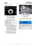
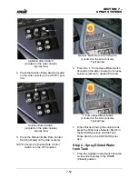
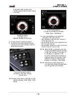
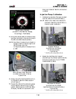
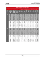
2. Press the Tank Valve Selector Switch
(located on the side console) in the UP
(Main Tank) position.
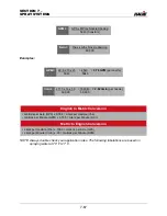
3. Press the Boom Solution Valve Switches
(located on the side console) in the ON
position.
NOTE: Each Boom Solution Valve Switch is
equipped with an indicator light and
will illuminate when the
corresponding Boom Solution Valve
is OFF.
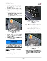
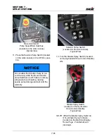
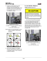
4. Press the Master Spray Switch (located
on the Hydrostatic Drive Control Handle)
in the ON position.
5. Continue spraying until all diluted water
is removed from tank.
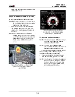
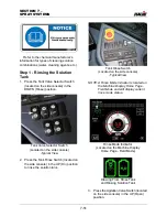
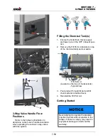
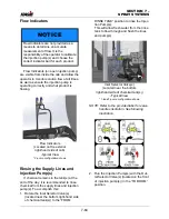
Step 3 - Rinsing the Boom and
Nozzles
1. Press the Tank Valve Selector Switch
(located on the side console) in the
DOWN (Rinse) position.
NOTE: When rinsing the boom and nozzles,
ensure the Boom Solution Valve
Switches (located on the side
console) are in the ON position
before activating the Tank Rinse
Switch.
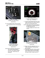
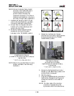
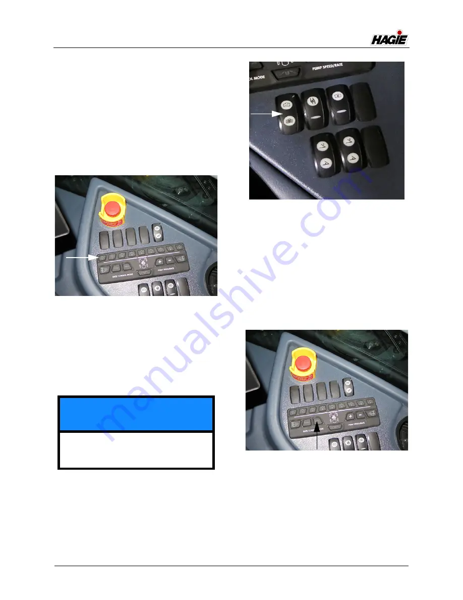
2. Press the Manual (MAN) Rate Control
Switch (located on the side console).
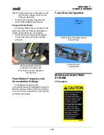
3. Press the “
+
” Pump Speed/Rate Switch
(located on the side console) to increase
the solution pressure to desired PSI
(bar).
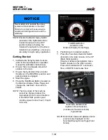
NOTICE
Do not allow the solution pump to run dry
for a prolonged period of time. Failure to
comply may result in pump damage.
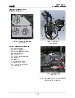
Boom Solution Valve Switches
(Located on the side console)
-Typical View
Tank Valve Selector Switch
(Located on the side console)
-Typical View
Manual “MAN” Rate Control Switch
(Located on the side console)
-Typical View
Summary of Contents for STS/DPS Series
Page 2: ...5 DASH AUTO...
Page 5: ...Troubleshooting 10 38...
Page 52: ...SECTION 2 SAFETY AND PRECAUTIONS 2 15 650210 Located on each NORAC sensor...
Page 380: ...NOTES 5 DASH AUTO...
Page 381: ...NOTES 5 DASH AUTO...
Page 382: ...NOTES 5 DASH AUTO...


