


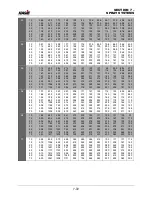


SECTION 7 –
SPRAY SYSTEMS
7-59
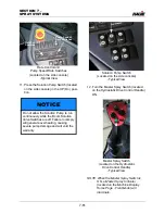
NOTE: Ensure the Master Spray Switch
(located on the Hydrostatic Drive
Control Handle) is in the OFF
position before activating the
Solution Pump Switch or the Boom
Solution Valve Switches, unless you
are ready to begin spray application.
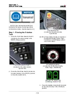
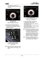
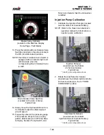
1. Calibrate the Spray System Console
(refer to the manufacturer’s operation
manual for calibration instructions).
2. Ensure there is adequate amount of
solution in the chemical tank(s) and
water in the main tank.
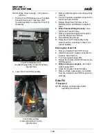
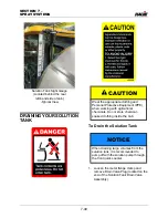
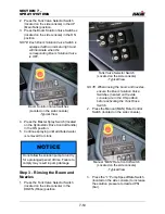
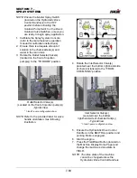
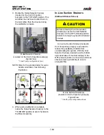
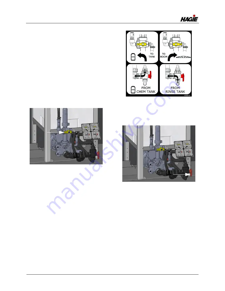
3. Rotate the Outlet Selector Valve(s)
(located on the front of injection
pump(s)) to the “TO BOOM” position.
NOTE: Refer to the provided label for valve
handle orientation. See following
illustration.
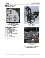
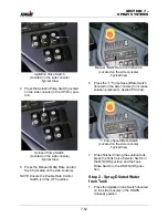
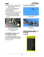
4. Rotate the Inlet Selector Valve(s)
(located near the bottom right-hand side
of chemical tank(s)) to the “FROM
CHEM TANK” position.
5. Ensure the Hydrostatic Drive Control
Handle is in the NEUTRAL position and
parking brake is engaged.
6. Start the engine.
7. Press the Field/Road Button (located on
the Machine Display Home Page) and
change the machine’s drive state to
FIELD.
NOTE: The drive state of the machine
cannot be changed unless the
Hydrostatic Drive Control Handle is
Outlet Selector Valve(s)
(Located on the front of injection pump(s))
-Typical View
* 1-tank/1-pump configuration show
Inlet Selector Valve(s)
(Located near the bottom
right-hand side of chemical tank(s))
-Typical View
* 1-tank/1-pump configuration show
Summary of Contents for STS/DPS Series
Page 2: ...5 DASH AUTO...
Page 5: ...Troubleshooting 10 38...
Page 52: ...SECTION 2 SAFETY AND PRECAUTIONS 2 15 650210 Located on each NORAC sensor...
Page 380: ...NOTES 5 DASH AUTO...
Page 381: ...NOTES 5 DASH AUTO...
Page 382: ...NOTES 5 DASH AUTO...


