


9-35
SECTION 9 –
MAINTENANCE AND STORAGE
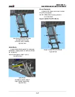
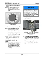
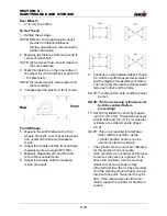
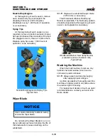
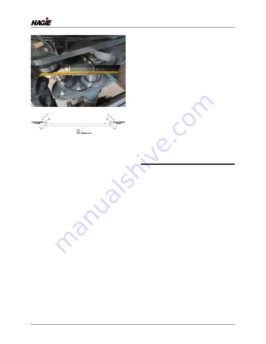
11. With the cylinders centered, adjust the
tie-rods (located on the cylinder rods)
until they line up with the bolt-down hole
(located on the lower air bag plate).
12. Turn the tie-rod one more full turn to
achieve desired amount of toe-in.
•
When the rod ends are turned the final
turn (to establish the desired amount of
toe-in), the rod ends turn in opposite
directions to get each wheel in toe.
•
If the amount of threads showing on the
left and right-hand rod ends differ by
more than four (4) threads, repeat previ-
ous Steps 1-12. If the difference
remains, there may be a tolerance issue
in the leg assembly.
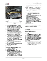
13. Pry wheel in to allow rod end securing
bolt to be inserted.
14. Insert bolt and torque main bolt and cyl-
inder jam nut to 190 ft-lbs.
Rear Wheels
NOTE: Rear wheels should be set to 0.0”
(0.0 cm) toe in/out.
15. Repeat previous Steps 1-9.
16.
(Non-AWS Machines) -
Set tie rod
assembly to match up with the bolt-down
hole (located on the lower air bag plate).
Insert bolt and secure to the proper
torque specification (refer to “Torque Val-
ues” provided in the
Introduction Section
elsewhere in this manual for further infor-
mation).
17.
(AWS Machines)
- Repeat Step 10, cen-
tering the rear cylinders at 4.4” (11.2
cm). Insert bolt and torque main bolt and
cylinder jam nut to 190 ft-lbs.
NOTE: The cylinder sensors must be
calibrated for this position to be
accurate.
•
The machine should be driven and toe
(front and rear) rechecked.
•
Front steering cylinders must be in
phase when toe setting is checked.
•
Failure to hold toe setting could indicate
the presence of air in the cylinders.
•
Repeat the cylinder bleeding procedure,
if necessary.
Further Information
Contact your local John Deere dealer if
additional assistance is needed.
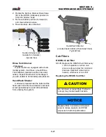
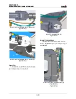
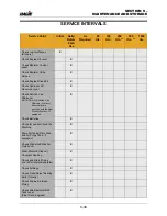
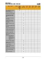
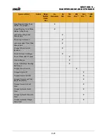
SERVICE -
MISCELLANEOUS
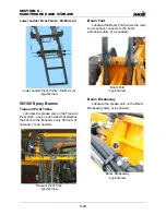
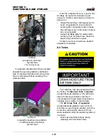
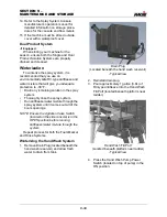
Air Bags
The Air Bags (one located on each leg)
provide a smooth, consistent ride quality. A
ride control valve increases/decreases
compressed air into the air bags to maintain
ride height position as load or wheel position
changes with ground level for each leg
independently.
NOTE: The front air bags are larger capacity
to accommodate heavier loads for
various front end attachments, yet
maintain a smooth ride.*
10.A
Summary of Contents for STS/DPS Series
Page 2: ...5 DASH AUTO...
Page 5: ...Troubleshooting 10 38...
Page 52: ...SECTION 2 SAFETY AND PRECAUTIONS 2 15 650210 Located on each NORAC sensor...
Page 380: ...NOTES 5 DASH AUTO...
Page 381: ...NOTES 5 DASH AUTO...
Page 382: ...NOTES 5 DASH AUTO...


