10-13
SECTION 10 –
MISCELLANEOUS
Unfolding the Boom for Storage
The booms must be partially open for
stability when unattached from the machine.
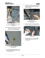
Unfold the booms approximately 10-20
°
(from folded position) while maintaining
sufficient clearance for repositioning during
reattachment. This position will allow the
booms to sit level with the transom without
causing excessive stress on either part. It will
also keep the weight from shifting too much
in either direction (rearward or forward),
which could cause the boom to tip over and/
or difficulty in connecting or disconnecting
the attachment.
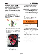
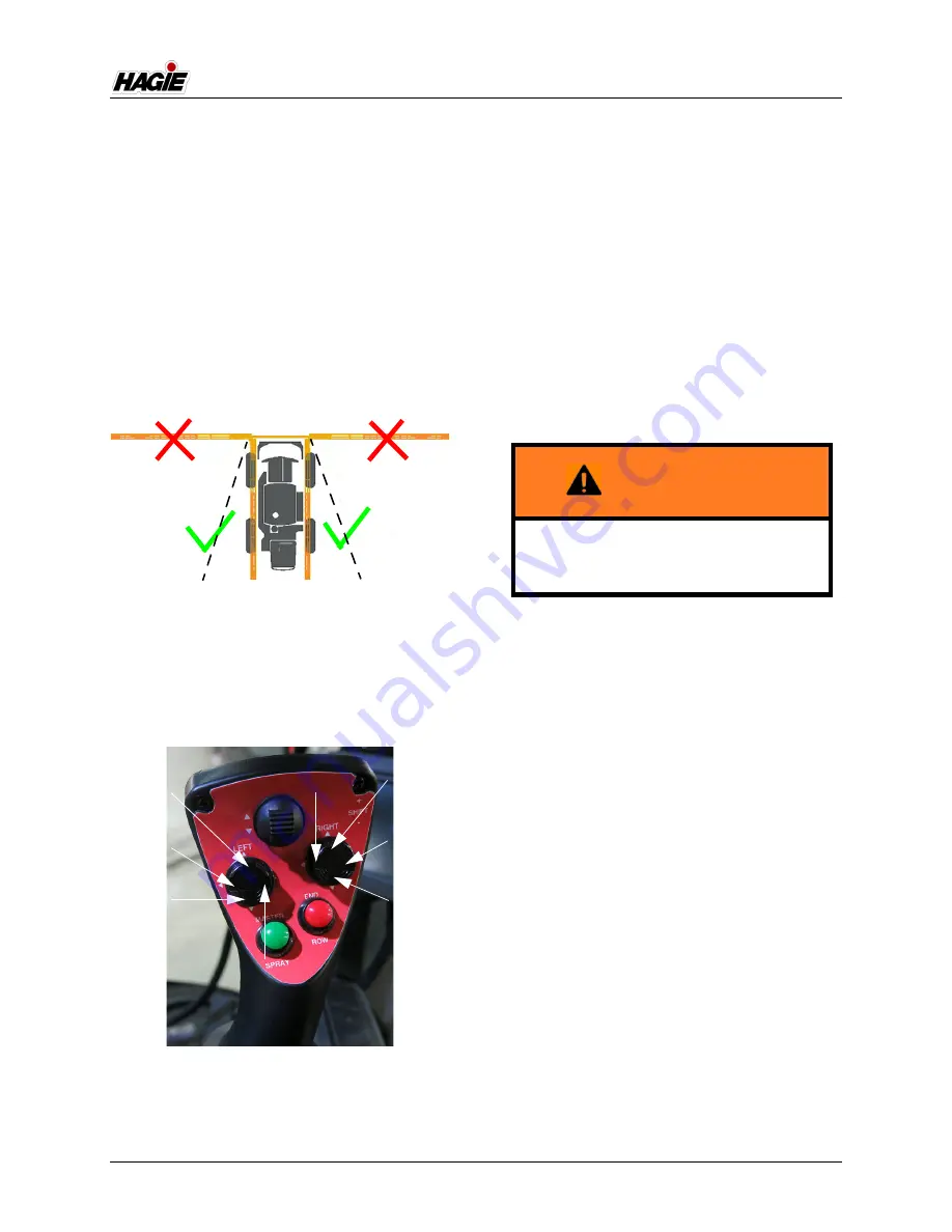
1. Press and hold the corresponding Left
and Right Boom Switches (located on
the Hydrostatic Drive Control Handle) in
the UP position to remove boom wings
from cradles.
2. Press and hold the corresponding Left
and Right Boom Switches in the OUT
position to unfold the boom wings until
partially
open.
NOTE: Booms only need to be unfolded far
enough to clear the boom cradles
and lower (e.g. enough to clear the
front tires and allow room for steering
to line up the boom). Do NOT fully
extend.
3. Lower the boom and secure the boom
stands (if equipped) in the DOWN posi-
tion.
See “Boom Stands” elsewhere in this
section for further information.
4. Press and hold the corresponding Left
and Right Boom Switches in the DOWN
position to point boom tips down (until
tips touch the ground).
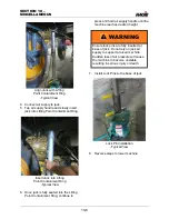
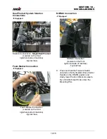
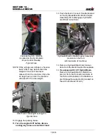
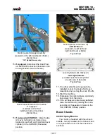
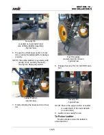
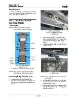
5. Disengage the Quick-Tach Lock Assem-
blies by pulling the Lock Pins (located on
the front left and right-hand side of
machine) OUT as far as it will go until it
is in the “lock-out” position.
NOTE: “Lock-out” position prevents re-
locking while attaching or detaching
the attachment.
NOTE: If necessary, adjust the level
cylinders to free the Lock Pins.
-Typical View
Left and Right-Hand Boom Switches
(Located on the Hydrostatic
Drive Control Handle)
-Typical View
• Right
Boom
OUT
• Right
Boom
DOWN
• Right
Boom
UP
• Right
Boom
IN
• Left
Boom
UP
• Left
Boom
OUT
• Left
Boom
IN
• Left
Boom
DOWN
WARNING
Lower boom to the ground before
disengaging the Quick-Tach Lock
Assemblies.
Summary of Contents for STS/DPS Series
Page 2: ...5 DASH AUTO...
Page 5: ...Troubleshooting 10 38...
Page 52: ...SECTION 2 SAFETY AND PRECAUTIONS 2 15 650210 Located on each NORAC sensor...
Page 380: ...NOTES 5 DASH AUTO...
Page 381: ...NOTES 5 DASH AUTO...
Page 382: ...NOTES 5 DASH AUTO...


