SECTION 10 –
MISCELLANEOUS
10-28
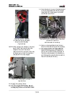
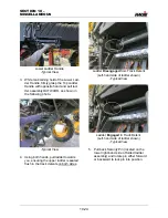
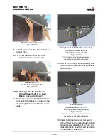
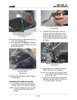
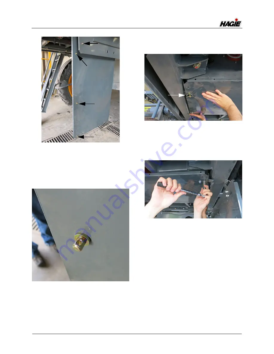
NOTE: Ensure each Hanger Pin opening is
facing UP (toward length of panel),
as shown in the following photo.
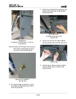
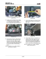
6. On opposite side of machine, remove
previously installed Securement Pins
(from Hanger Pins).
7. Lift Panel 4 and align hole openings with
Hanger Pins. Attach by reinserting the
Securement Pins.
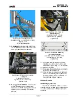
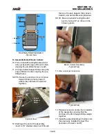
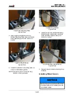
8. Using a 1/2” wrench or socket, tighten
the belly shield nuts and bolts, as shown.
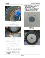
9. Lift and secure Panels 5 and 6, tighten-
ing belly shield nuts and bolts in the
same manner.
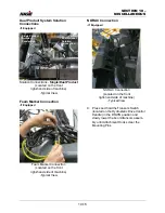
Hanger Pins
(Install pins onto Panels 4, 5, and 6)
-Typical View
Hanger Pin Installation
-Typical View
Securement Pin
(Installed into Hanger Pin)
-Typical View
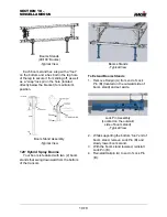
-Typical View
Summary of Contents for STS/DPS Series
Page 2: ...5 DASH AUTO...
Page 5: ...Troubleshooting 10 38...
Page 52: ...SECTION 2 SAFETY AND PRECAUTIONS 2 15 650210 Located on each NORAC sensor...
Page 380: ...NOTES 5 DASH AUTO...
Page 381: ...NOTES 5 DASH AUTO...
Page 382: ...NOTES 5 DASH AUTO...


