SECTION 3 –
CAB
3-34
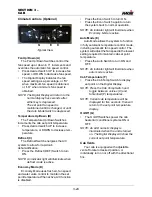
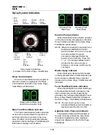
Spray System Indicators
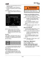
Rinse Tank Indicator
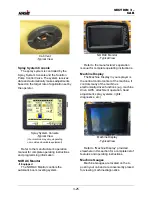
When the Tank Rinse Switch (located on
the side console) is depressed, the Rinse
Tank Indicator (located on the Home Page -
Field Mode) will illuminate.
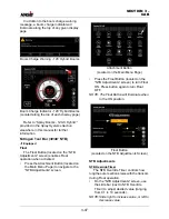
Main Tank Rinse Mode Indicator
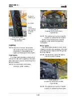
The Tank Valve Selector Switch (located
on the side console) allows the operator to
pull from either the main tank or the rinse
tank. The Main Tank Rinse Mode Indicator
(located on the Home Page - Field Mode) will
illuminate to display current status.
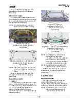
Solution Pump Indicator
When the Solution Pump Switch (located
on the side console) is depressed, a Solution
Pump Indicator (located on the Home Page -
Field Mode) will illuminate.
NOTE: When the Solution Pump Switch and
the Manual (MAN) Rate Control
Switch (located on the side console)
are both enabled, the pump
command is displayed below the
Solution Pump Indicator. Press the
“+” or “-” Pump Speed/Rate Switch
(located on the side console) to
increase or decrease solution pump
command.
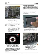
Master Spray Indicator
When the Master Spray Switch (located
on the Hydrostatic Drive Control Handle) has
been activated, a Master Spray Indicator
(located on the Home Page - Field Mode) will
illuminate.
Fence Row/Rear Nozzle Indicators
When the left/right Fence Row Switch(es)
or the Rear Nozzle Switch (located on the
side console spray section keypad) are
activated, the corresponding left/right Fence
Row or Rear Nozzle Indicators (located on
the Home Page - Field Mode) will illuminate.
NOTE: The rear track nozzle is only
activated if the Rear Nozzle Switch is
depressed and Section 5 is ON.
Agitation Valve Pressure Indicator
The Agitation Valve Switch (located on
the side console) controls the rate of flow
through the Agitation System. Agitation
pressure is displayed on the Home Page -
Field Mode.
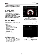
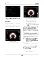
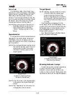
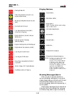
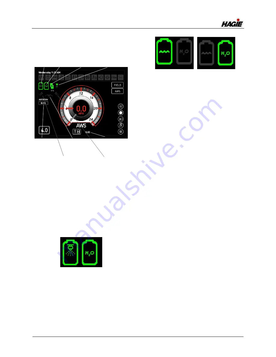
Spray System Indicators
(Located on the Home Page - Field Mode)
• Master
Spray
Indicator
• Solution
Pump
Indicator
• Agitation
Valve
Pressure
Indicator
• Rinse
Tank
Indicator
• Main
Tank
Rinse
Mode
• Spray Time
Indicator
• Left
Fence
Row
Indicator
• Rear
Nozzle
Indicator
• Right
Fence
Row
Indicator
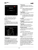
Drawing From Rinse Tank
and Rinsing Solution Tank
Drawing From
Rinse Tank
Drawing From
Main Tank
Summary of Contents for STS/DPS Series
Page 2: ...5 DASH AUTO...
Page 5: ...Troubleshooting 10 38...
Page 52: ...SECTION 2 SAFETY AND PRECAUTIONS 2 15 650210 Located on each NORAC sensor...
Page 380: ...NOTES 5 DASH AUTO...
Page 381: ...NOTES 5 DASH AUTO...
Page 382: ...NOTES 5 DASH AUTO...

