background image

5-2

SECTION 5 –

HYDRAULIC SYSTEMS

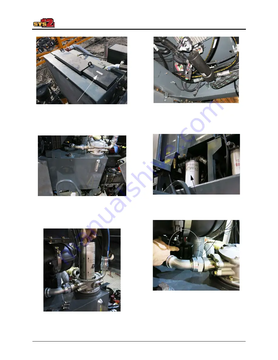
Oil Cooler

(Located near rear of machine -

open hood to access)

-Typical View

Hydraulic Oil Reservoir

(Located on left-hand side of

machine - open hood to access)

-Typical View

Return Filter

(Located inside filter housing

on left-hand side of machine)

-Typical View

Pressure Filter

(Located beneath right-hand side of 

machine - lower metal shield to access)

-Typical View

Case Drain Filter

(Located on left-hand side of machine)

-Typical View

Breather Cap

(Located on left-hand side of

machine near return filter housing)

-Typical View

Summary of Contents for STS12i Combo

Page 1: ...SAFETY AND PRECAUTIONS Intended Use 2 1 Safety Precautions 2 1 Seat Belt 2 6 Rotating Beacons 2 7 Emergency Stop 2 7 Emergency Exit 2 8 Fire Extinguisher 2 8 First Aid Kit 2 9 Roll Over Protection Str...

Page 2: ...Solution Tank 7 41 Draining Your Solution Tank 7 45 Rinse System 7 46 Chemical Injection System 7 50 Foam Marker System 7 56 Application 7 57 8 MAINTENANCE AND STORAGE Service Fluids 8 1 Service Filte...

Page 3: ...ght to make changes in the design and material of any subsequent sprayer without obligation to existing units Thank you for choosing a Hagie sprayer and we ensure you of our continued interest and sup...

Page 4: ...pecial mention of or remark on SERVICE AND ASSISTANCE For service and assistance please contact Hagie Manufacturing Company 721 Central Avenue West P O Box 273 Clarion IA 50525 0273 515 532 2861 OR 80...

Page 5: ...behind rear leg Engine The engine has an identification plate mounted on top of engine near the oil fill port that provides engine serial number as well as other manufacturer information Refer to you...

Page 6: ...plate mounted on the front of hub that provides hub serial number as well as other manufacturer information including gear ratio Refer to your Parts Manual for specific part number Hydraulic Pumps Top...

Page 7: ...bottom right hand side of transom Aluminum Spray Booms 120 132 The aluminum spray boom serial number is stamped on the lower right hand side of fixed transom Steel Spray Boom Serial Number Typical Vie...

Page 8: ...C2 86 104 18 218 4 cm 264 2 45 7 cm 86 104 18 218 4 cm 264 2 45 7 cm 86 104 18 218 4 cm 264 2 45 7 cm 86 104 18 218 4 cm 264 2 45 7 cm D Static Loaded Hub Height 38 3 8 97 5 cm 38 3 8 97 5 cm 38 3 8 9...

Page 9: ...wheel individual auto air ride Shipping Width 144 365 8 cm with 90 100 boom 177 449 6 cm with 120 132 boom Approximate Dry Weight 24 210 lbs 10 981 kg machine only 28 710 lbs 13 022 kg with 90 boom 2...

Page 10: ...sions may vary depending on boom and tire options Detail Description Specification A Wheel Base 166 421 6 cm B Static Loaded Hub Height 38 3 8 97 5 cm C Overall Sprayer Height from middle of GPS unit...

Page 11: ...ration values in the spaces provided below Units US Acres SI Hectares Turf 1 000 sq ft 92 sq m Speed Sensor SP1 Wheel Speed SP2 Radar GPS Control Type Liquid Spray Gran 1 Single Belt Bed Gran 2 Split...

Page 12: ...ilter Minder Slow Idle 850 RPM Fast Idle no load 2300 RPM Hydrostatic Drive Hydrostatic Pump Danfoss H1 Series Drive Train All Wheel 4 Wheel Drive Speed Ranges Speed Ranges 1 20 operator selected Hydr...

Page 13: ...ion Tank Standard 1200 gal 4542 5 L stainless steel Agitation Jet type with electric valve variable control General Spray System Pump Centrifugal hydraulically driven with proportional control valve S...

Page 14: ...r lights Spray Boom Indicators located on boom if equipped 1 oval white 2 oval amber 9 oval red Cab and Instruments Sound Level cab interior 86 dBA maximum Cab General Tilt steering wipers washers dua...

Page 15: ...m including block lines and radiator Tier 4 Final 14 gallons 53 L ethylene glycol Tier 3 12 5 gallons 47 L ethylene glycol Diesel Exhaust Fluid DEF Tank Tier 4 Final Engines 10 gallons 37 L Hydraulic...

Page 16: ...Ultra Sprayer 170A8 B 75 14 3 13 200 80 9 37 5 244 305 520 85R46 Michelin Agribib 158A8 28 20 3 10 030 80 7 36 2 240 441 TIRE SPECIFICATIONS METRIC Size Make Model Load Rating Weight Speed Air Pressur...

Page 17: ...N A N A N A N A N A N A N A N A 9 500 380 90R46 3 280 4 620 5 430 6 240 6 500 6 950 7 300 7 770 8 180 380 90R54 3 000 3 640 4 300 4 800 5 520 6 000 6 600 6 950 7 400 520 85R46 4 610 5 510 6 420 7 320...

Page 18: ...084 VF380 90R46 N A N A N A N A N A N A N A N A 4 309 380 90R46 1 487 2 095 2 463 2 830 2 948 3 152 3 311 2 524 3 710 380 90R54 1 360 1 651 1 950 2 177 2 503 2 721 2 993 3 152 3 356 520 85R46 2 091 2...

Page 19: ...not cover normal maintenance such as engine tune ups adjustments inspections nor any consumables such as tires rubber products solution system valves wear parts wiper blades etc Hagie Manufacturing Co...

Page 20: ...e components Exhaust System upstream of last Aftertreatment Exhaust gas piping from turbocharger out to the last Aftertreatment device Exhaust Aftertreatment Urea Quality Sensor Urea Level Sensor Urea...

Page 21: ...ts attachment or any sprayer equipment Do not make any modifications such as but not limited to weldments add ons adaptations or changes from the original design of the sprayer Such modifications may...

Page 22: ...never allowed to ride outside of the cab Remove Paint Before Welding or Heating Avoid toxic fumes and dust Hazardous fumes can be generated when paint is heated by welding soldering or using a torch D...

Page 23: ...ing that may be blown or drawn into moving parts Do not activate the parking brake while the machine is in motion Bring machine to a gradual stop to avoid sudden downward decent Reduce speed for icy w...

Page 24: ...injury If you spill on yourself Flush affected area with cold water and remove contaminated clothing and shoes immediately Continue to flush the area for a minimum of 15 minutes Call a physician While...

Page 25: ...icient force to pene trate your skin possibly resulting in seri ous injury This fluid may also be hot enough to burn Always lower the load or relieve the pressure before repairing a hydraulic oil leak...

Page 26: ...s cold the valve response is not as fast or accurate Therefore when having to lift the weight the cylin der will move slower but in trying to suspend the weight the weight may cause faster movement as...

Page 27: ...the side console provides a quick and positive method for stopping the engine in an emergency situation When the E Stop Switch is depressed it locks in position and removes the ignition signal to shu...

Page 28: ...cut the seat belt FIRE EXTINGUISHER Your machine is equipped with a Fire Extinguisher located along the platform on the left hand side of machine In the event that use of the Fire Extinguisher is req...

Page 29: ...b has met specific testing requirements and is compliant with Occupational Safety and Health Administration OSHA and International Organization for Standardization ISO regulations NOTE The ROPS Vehicl...

Page 30: ...nting hard ware ROPS must be inspected immediately after any type of collision roll over or impact If any damage is evident the ROPS must be removed from service repaired and or replaced When a ROPS i...

Page 31: ...2 11 SECTION 2 SAFETY AND PRECAUTIONS Safety Decal Locations 650164 Located on rear left hand cab post 650174 Located on top of radiator 650176 Located on rear right hand cab post 650178 2 Quick Tach...

Page 32: ...around booster terminals 650296 Located on rear frame near booster terminals 650339 Located on front cross member 650348 Located on air tank 650401 Located near side fill and front fill RISK OF INJURY...

Page 33: ...gines only 650434 Located near reversible fan 650462 Located near radiator cap 650474 Located on rear right hand cab post CAUTION CUTTING SEVERING OF FINGERS OR HAND DO NOT PLACE FINGERS OR HAND NEAR...

Page 34: ...near fuel cap 650850 Front Fill Located on solution tank near fill lid Side Fill Located on inductor tank lid 650851 Located on underside of belly shields 90 100 Boom Decals 650203 Located on transom...

Page 35: ...20 132 Boom Decals 650203 Located on fixed transom 650204 6 Located near each fold point 650208 Located on fixed transom 650210 5 Located on each NORAC sensor 650390 2 Located on cylinder near accumul...

Page 36: ...0256 READ OPERATOR S MANUAL WEAR EYE PROTECTION WEAR EAR PROTECTION ELECTRICAL LOCK OUT HOT SURFACE DO NOT TOUCH EXHAUST TUBE WHILE ENGINE IS RUNNING ALLOW ADEQUATE TIME FOR THE ENGINE TO COOL DOWN BE...

Page 37: ...maintaining desired armrest position re tighten bolts Armrest Tilt Dial B Tilts armrests Roll Armrest Tilt Dial located on side of operator s seat INWARD towards opera tor to tilt armrest DOWN Roll A...

Page 38: ...mrest Pull and hold Armrest Height Length Adjuster and slide forward or rearward Release adjuster when armrest is in desired position Lumbar Knob J Adjusts lumbar curvature Rotate Lumbar Knob INWARD t...

Page 39: ...Cool Temperature Switch C Switches heat cool temperature to high low or off settings Press Heat Cool Temperature Switch UP for HIGH heat or cool Press Heat Cool Temperature Switch DOWN for LOW heat or...

Page 40: ...L Locks or unlocks lateral isolation Pull Lateral Lockout Isolator UP to lock isolation Push Lateral Lockout Isolator DOWN to unlock isolation Ride Firmness Lever M Adjusts ride suspension Pull Ride...

Page 41: ...n Signal Indicator Left E Highway Running Lights Indicator F High Beams Indicator G Turn Signal Indicator Right H Steering Wheel Telescope Adjust Handle I Steering Column Tilt Adjust Button Knee Angle...

Page 42: ...ng Lights Switch located on steering column in the DOWN On position Press the Hazard Warning Lights Switch in the UP Off position to deactivate Highway Running Lights The Highway Running Lights locate...

Page 43: ...eel lift the Steering Wheel Telescope Adjust Handle located to the right of the steering col umn UP to loosen enough to freely move the steering wheel With the handle loosened adjust steering wheel to...

Page 44: ...ured for ease of exiting and entering the cab With your foot on the Steering Column Release Pedal located on the lower left hand side of the steering column push pedal DOWN and move the steering col u...

Page 45: ...of the Turn Signal Lever INWARD Windshield Washer The Windshield Washer Switch is located on the end of the Turn Signal Lever To apply washer fluid press and hold switch in the IN position NOTE Ensur...

Page 46: ...ft Nitrogen Tool Bar Operating Switches if equipped C Boom Solution Valve Switches D Fence Row Switch Left E Rate Control Switches F Rear Nozzle Switch G Pump Speed Rate Switches H Fence Row Switch Ri...

Page 47: ...1 SECTION 3 CAB A B C D E F G H Typical View Typical View I J K L M N O P Version 1 Front View Typical View Q R S T U Version 2 Front View Typical View R S T U Q V Version 1 Rear View Typical View V W...

Page 48: ...d positive method for stopping the engine in an emergency situation NOTE DO NOT use this button for non emergency stopping or as a parking brake Version 2 Side View Typical View W X Typical View Y Typ...

Page 49: ...e first section Each Boom Solution Valve Switch is equipped with an indicator light and will illuminate red when manually turned off Refer to the Spray Systems Section elsewhere in this manual for fur...

Page 50: ...he Pump Speed Rate Switches located on the side console allow you to increase or decrease flow rate through the spray system NOTE When the MAN Rate Control Switch is pressed the Pump Speed Rate Switch...

Page 51: ...he Agitation Valve Switch located on the side console controls the rate of flow through the Agitation System Refer to the Spray Systems Section elsewhere in this manual for further information Rinse S...

Page 52: ...NG When operating or positioning the booms observe the following safety precautions to avoid serious injury or death Select a safe area before folding unfolding booms Clear area of personnel Check for...

Page 53: ...must be engaged before engaging the starter To engage the starter turn the key to the START position and hold momentar ily until the engine engages If the engine does not engage after 15 seconds turn...

Page 54: ...d in which it travels parking brake engagement Version 1 and ladder extension retraction It is also used to control the spray booms end row management master spray and shift up down speeds Refer to th...

Page 55: ...Down Switches The Shift Up Down Switches located on the Hydrostatic Drive Control Handle are used for speed range selection Refer to Hydrostatic Drive provided in the Engine and Drive Systems Section...

Page 56: ...s DOWN turtle icon to decrease the speed the more the engine will speed up or slow down Parking Brake Switch Hydrostatic Drive Control Handle Version 2 If Equipped If your machine is equipped with Ver...

Page 57: ...radio chan nels or CD MP3 selections Power Ports 12 Volt Four 4 Power Ports three located on the inward side console panel and one located along the lower left hand side of operator s seat are provide...

Page 58: ...ay G Machine Gauges H Section Indicator Display 12V Power Ports and Aux 2 Audio Input Connection Located on the inward side console panel Typical View 12V Power Ports Aux 2 Audio Input Connection Typi...

Page 59: ...age 1 5 2nd page 6 8 6 Turns the registration pages Registration No 6 press 6 then press 1 Registration No 7 press 6 then press 2 Registration No 8 Press 6 then press 3 2 Press and hold the selected P...

Page 60: ...Temperature Setting Dial clockwise to increase temperature Rotate the Temperature Setting Dial counter clockwise to decrease temperature Air Conditioner Switch C To activate the air conditioner press...

Page 61: ...auto mode is active Cab Temperature F Press the Cab Temp Switch to display set point on the Digital Display NOTE Press the Cab Temp Switch and toggle between celsius C and fahrenheit F temperatures N...

Page 62: ...Gauges are located on the A post in your cab and are conveniently placed for viewing machine diagnostics Section Indicator Display The Section Indicator Display allows you to view system status for t...

Page 63: ...erosol filtration system to provide continuous positive pressure in the cab by reducing exposure to harmful particulates NOTE The filtration system will activate automatically approximately 10 seconds...

Page 64: ...ction elsewhere in this manual for information on replacing the charcoal filter and cleaning the recirculation filter Portable Electric Cooler If Equipped Your machine may be equipped with a Portable...

Page 65: ...erior Lights Diagnostics Machine Display Page Settings The Machine Display is featured with six display pages Home Page Road Mode Home Page Field Mode Auxiliary Controls Page Video Camera Page Machine...

Page 66: ...ield Road Speed Settings First Range Top Speed Last Range Top Speed Number of Ranges AWS Shutoff Speed Field Speed Set tings only Machine Adjustments Auto Steer SASA T Delay On SASA T Delay Off A Stee...

Page 67: ...mum Section 1 Force Float 60 NTB Adjustments only Machine Setting Security To Lock Machine Settings Press the Locked Parameters Button located on the Settings Page On the Change Locked Parameters scre...

Page 68: ...lay page and illuminate to inform you of a specific situation Warning Light Indicator When a system error requires attention a Machine Warning Light Indicator located on the top left hand side of each...

Page 69: ...Lighting Adjustment Day Time Night Time To Adjust the Display Keypad and Console Lighting Press the Brightness Button located on the Settings Page On the Brightness screen press desired Day Time or N...

Page 70: ...e Color Language Display Animation Press the Display Button located on the Settings Page On the Display Settings screen press EDIT next to Animations and select Yes to enable animations or No to disab...

Page 71: ...Buttons Press OK Machine Information Machine information such as total engine machine hours software version attachment information and machine serial number are located on the Machine Information scr...

Page 72: ...ress the Field Lights Button s FLD1 and or FLD2 to turn Field Lights ON Press button s again to turn Field Lights OFF NOTE Turn Field Lights OFF before entering a public roadway NOTE The ignition key...

Page 73: ...Camera Your machine is equipped with a Video Camera for your convenience when operating the machine in reverse and is located on the rear of the sprayer On the Video Camera Page press desired camera d...

Page 74: ...nd hold the Arrow Buttons to fine tune display angle Press OK Settings Press the Settings Button located on the Camera Settings screen On the Camera Adjustable Settings screen press EDIT next to desir...

Page 75: ...5 mph 0 8 km h The machine is featured with three 3 Drive States ROAD FIELD and FAULT The Drive State helps the machine determine what kind of work it is meant to do field work or transport work Road...

Page 76: ...peed in which the machine travels is displayed on the Home Page Road and Field Mode The unit of measure can be viewed as miles per hour MPH or kilometers per hour km h To Change the Unit of Measure Pr...

Page 77: ...Speed according to the newly entered values Throttle Throttle Control Slope Determines how fast engine speed increases when the Throttle Switch located near the Hydrostatic Drive Control Handle is pre...

Page 78: ...tting Values Press the Throttle Button located on the Settings Page On the Throttle Settings screen press EDIT next to the desired Throttle set ting Enter desired value then press ACCEPT Press OK Refe...

Page 79: ...n ON but the AWS indicator will turn OFF and the machine will be operating in conventional steering mode When conditions are met again AWS will automatically activate and the AWS indicator will illumi...

Page 80: ...e Auto Steer NOTE A larger sensitivity number means that the steering wheel will need to be turned farther and faster for Auto Steer to disengage To Change Auto Steer Setting Values Press the Auto Ste...

Page 81: ...ogrammed for use of various functions including All Wheel Steer Auto Steer Master Spray and NORAC Enable To Program the End Row Management Switch Press the End Row Management Button located on the Set...

Page 82: ...to desired End Row Management setting Pause Before Activate Display When Active Enable Single Press Enable Press and Hold Enter desired value setting then press OK Press OK Refer to Spray Booms provi...

Page 83: ...on the Auxiliary Controls Page NOTE This button is marked with two arrows and will navigate to the Tread Adjustment Page On the Tread Adjustment Page select the tread that you wish to simultaneously a...

Page 84: ...ervice interval has been reached a screen message will appear on the Machine Display informing you which service item requires attention Refer to the Maintenance and Storage Section elsewhere in this...

Page 85: ...stance is needed NOTE When this warning message appears the machine may be severely limited in engine and hydraulic functions to prevent possible damage to those systems DP A DP B Gauges The DP A and...

Page 86: ...r screen allows you to view CAN messages on each of the CAN networks CAN1 CAN2 CAN3 CAN1 Engine CAN2 Primary Secondary Controllers CAN3 Diagnostics Primary Controller NOTE CAN3 by itself does not go t...

Page 87: ...ting Press the Measure Button located on the Settings Page Select system On the Press to Select Signals to Mea sure screen press the UP or DOWN Arrow Buttons to toggle to desired parameters NOTE Singl...

Page 88: ...Press the More Button to display fault description Press the Clear Faults Button to remove faults after the fault issue has been resolved Press OK to confirm NOTE System Faults will continue to appea...

Page 89: ...e fan will automatically return to Normal Operation when the reverse cycle is complete Refer to Reversible Fan provided in the Hydraulic Systems Section elsewhere in this manual for further informatio...

Page 90: ...tch located on the side console is activated the Rinse Mode Indicator located on the Home Page Field Mode will display either OFF BOOM or TANK Agitation Valve Pressure Indicator The Agitation Valve Sw...

Page 91: ...d on the Auxiliary Controls Page Rolling Boom 120 132 Spray Booms The Roll Command Buttons located on the Auxiliary Controls Page will enable the boom to roll either clockwise or counter clockwise as...

Page 92: ...located on the Settings Page On the Spray Tip screen press the Custom Button On the Press to Select Droplet Size s screen select desired droplet size ranges NOTE Droplet size ranges may be selected b...

Page 93: ...tom of the Home Page Field Mode Efficiency EFF Rate The EFF Rate located on the bottom of the Home Page Field Mode displays the current spray efficiency value Spray time divided by the time spent in F...

Page 94: ...s screen press EDIT next to desired selection NTB Override Timer Float with Transom Down or One Tap Transom Up Enter select desired setting then press OK Press OK 60 NTB Setup Various 60 ft NTB adjust...

Page 95: ...aximum Right Section 3 Maximum Right Section 2 Maximum Section 1 Force Float Enter select desired setting then press OK Press OK Further Information Refer to your NTB operator s manual for complete fe...

Page 96: ...fuel leaks Cold Start Procedure 1 Engage the parking brake NOTE Refer to Hydrostatic Drive provided elsewhere in this section for further information 2 Turn the Ignition ON but DO NOT engage the start...

Page 97: ...od of at least five 5 minutes before operating the engine at a high RPM NOTE The engine must reach operating temperature and oil pressure must stabilize in the normal operating range before it is run...

Page 98: ...el Exhaust Fluid DEF that does not meet the specifications provided or to operate the machine with no DEF WARNING DEF contains urea Do not get the substance in your eyes In case of contact immediately...

Page 99: ...tem damage and will void the warranty NOTICE DEF CAN BE CORROSIVE TO CERTAIN MATERIALS Use only approved containers to transport or store DEF polyethylene and polypropylene containers recommended If D...

Page 100: ...alytic Reduction SCR DEF Dosing Module DEF Supply Module DEF Supply Module Filter DEF Quality Sensor DEF Suction Strainer Tier 4 Final Diesel Engine DEF Tank DEF Tank Capacity 10 Gallons 37 L DEF Dies...

Page 101: ...which is then converted into ammonia SCR Selective Catalytic Reduction The SCR is where the DEF reduces gaseous nitrogen oxide NOx to near zero levels by converting into nitrogen gas and water vapor D...

Page 102: ...erformance occurs remove drain plug located at bottom of tank to drain sediment from tank Remove and clean Suction Strainer ensuring the strainer is reinstalled correctly when finished NOTE Flush DEF...

Page 103: ...is low and flashes when the DEF falls below a very low level Operator should refill the DEF tank with DEF Flashing DEF Indicator Lamp with Check Engine Indicator Lamp Illuminates when theDEF level is...

Page 104: ...sume normal operation Exhaust System Cleaning Indicator Lamp with Check Engine Indicator Lamp If an Exhaust System Cleaning is not performedinatimelymannerafter the Exhaust System Cleaning Indicator L...

Page 105: ...Hydrostatic Drive System consists of four components Diesel Engine Hydrostatic Pump Wheel Motors and Wheel Hubs Hydrostatic Drive Components Cummins Diesel Engine Hydrostatic Pump Wheel Motors 4 Whee...

Page 106: ...difference in the placement of controls Version 1 allows the Parking Brake to engage disengage through the Hydrostatic Drive Control Handle moving the handle fully to the right For machines equipped...

Page 107: ...ing Brake Indicator located on the top left hand side of each Machine Display page will illuminate CAUTION Ensure the Hydrostatic Drive Control Handle is in the NEUTRAL position before engaging the pa...

Page 108: ...steering column and press the Parking Brake Switch in the DOWN Off position Deceleration Decel Pedal When nearing an end row and speed deceleration is desired press the Decel Pedal located on the low...

Page 109: ...ield Mode The Throttle Switch works with a timer to tell the engine how fast to run The longer the operator holds the switch in either direction press UP rabbit icon to increase the speed press DOWN t...

Page 110: ...nging the direction of the machine To move the machine forward slowly push the Hydrostatic Drive Control Han dle FORWARD NOTE The further the handle is moved forward the faster the machine will travel...

Page 111: ...n the front wheels turn one direction and the rear wheels turn in the opposite direction to create a tighter turn angle which allow the rear wheels to follow the front wheel tracks Operating your mach...

Page 112: ...eels turn Coordinated Steering All the wheels turn and do so where the rear tires follow in the front tires tracks AWS Components The Steering Cylinder internal position and External Proximity Sensors...

Page 113: ...machine s drive state is in Field mode 2 Press the AWS Button located on the Machine Display Home Page Field Mode to the ON illuminated position An AWS indicator located below the speedometer will ill...

Page 114: ...ine off the line intended because the rear wheels move back to straight posi tion and the total turning radius will change In the following illustration the two circles represent a full turn with AWS...

Page 115: ...ION 4 ENGINE AND DRIVE SYSTEMS AWS mode and switching from Auto Steer ON to OFF especially when turn ing Contact Hagie Customer Support with any questions you may have regarding the operation of the A...

Page 116: ...ump powers the Reversible Fan motor and control valve PC Pump The PC Pump powers the high pressure filter power steering attachments tread adjustment valve side fill valve AWS valve if equipped and th...

Page 117: ...ood to access Typical View Return Filter Located inside filter housing on left hand side of machine Typical View Pressure Filter Located beneath right hand side of machine lower metal shield to access...

Page 118: ...reservoir Typical View Solution Pump Located near center of machine Typical View View shown from top of machine Solution Pump Control Manifold Located near center of machine Typical View View shown fr...

Page 119: ...ct the radiator shroud mounting bolts to ensure that the radiator and shroud are firmly secured and unable to move during operation of the machine Loose shroud bolts can allow the fan WARNING Improper...

Page 120: ...JUSTMENT If Equipped Tread Width can be individually adjusted by pressing and holding the corresponding Tread Width Adjustment Button located on the Machine Display Auxiliary Controls Page to desired...

Page 121: ...on each leg The front legs use indicator decals while the rear legs use electronic sensors and dis play the readings on the Machine Dis play Auxiliary Controls Page to the left of the Tread Width Adj...

Page 122: ...th Version 2 a separate parking brake switch is located adjacent to the Hydrostatic Drive Control Handle which engages the Parking Brake and lowers the Ladder when activated Refer to specific operatin...

Page 123: ...hand side of the steering column and move the Hydrostatic Drive Control Handle to the LEFT Neutral position Hydrostatic Drive Control Handle Version 2 To raise the Ladder press and hold the Decel Peda...

Page 124: ...ION 65 WARNING WARNING Diesel engine exhaust and some of its constituents are known to the State of California to cause cancer and birth defects or other reproductive harm WARNING Battery posts termin...

Page 125: ...ngs equivalent to the following specifications Voltage 12V only CCA 30 seconds at 0 F 950 Reserve Capacity 185 minutes at 25 amps Storage Refer to Storage provided in the Maintenance and Storage Secti...

Page 126: ...or Cab Functions The following label is affixed beneath the side console remove tray to access and provides information on component fuse relay amperage ratings Circuit Breakers Fuses Interior Located...

Page 127: ...Exterior Lights System Functions The following label is affixed beneath the cab and provides information on component fuse relay amperage ratings Circuit Breakers Fuses Exterior Located beneath cab re...

Page 128: ...iew View shown from beneath machine Device Placement Pos Ref Device Part No D1 F01 Mini Fuse ATM 15UNP PEC D2 F02 Mini Fuse ATM 10UNP PEC D3 F03 Mini Fuse ATM 15UNP PEC D4 F04 Mini Fuse ATM 30UNP PEC...

Page 129: ...e ATM 15UNP PEC SP3 Mini Fuse ATM 20UNP PEC SP4 Mini Fuse ATM 30UNP PEC Device Totals Device Part No Amount Mini Fuse ATM 10UNP PEC 2 Mini Fuse ATM 15UNP PEC 3 Mini Fuse ATM 20UNP PEC 2 Mini Fuse ATM...

Page 130: ...er F07 20 Auxiliary Battery Power 1 F08 20 Front Fill F09 20 Auxiliary Battery Power 2 F10 20 Attachment Lights F11 15 Flasher Module F12 20 Foam Marker F13 20 Cab Pressure Fan F14 20 Side Fill F15 15...

Page 131: ...iliary Switched Power beneath cab F09 20 Chassis XA2 0 Power F10 20 Steering Column Battery Power F11 15 Rotating Beacons F12 20 Attachment Valve Power 2 F13 20 Chassis XA2 1 Power F14 20 Attachment V...

Page 132: ...beneath cab F39 20 Secondary Controller Power beneath cab F40 15 HVAC Clutch Relay Rating Amps Function CR01 35 Rotating Beacon Lights CR02 35 Wiper CR03 35 Wiper Washer CR04 35 Field Lights 1 CR05 2...

Page 133: ...amera Input Connections located beneath cab remove front panel to access are provided for the installation of add on video camera s Refer to Machine Display provided in the Cab Section elsewhere in th...

Page 134: ...UP position to remove boom wings from cra dles NOTICE Boom hose clamps must be installed initially before unfolding the spray booms Failure tocomply will result inthe solution hoses becoming obstructe...

Page 135: ...hose as shown 10 Install Boom Hose Clamp over top of the hose routing 11 Aligning Boom Hose Clamp hole with the Hose Routing Bracket hole install bolt previously removed in Step 8 through the clamp a...

Page 136: ...main boom is in cradle Do not operate machinewith one boom out of cradle and the other boom in cradle Ensure booms are folded and in cradle before transporting the machine Boom Hose Clamp Installation...

Page 137: ...ons of a 60 80 90 ft spray boom adjusting the spray valves and shutting off the outer sections turns it into an 80 ft spray boom see the following illustrations Refer to the Spray System Console calib...

Page 138: ...Outer Boom Breakaway Press and hold the Reset Breakaways Button Located on the Machine Display Auxiliary Controls Page until the outer boom sections are in the LOCKED posi tion NOTE On 90 ft spray bo...

Page 139: ...s until the boom is parallel with the ground 90 ft Spray Booms Press and hold the Boom Extension Switch located on the side console in the UP position to unfold the left and right boom extensions all...

Page 140: ...oth left and right boom extensions move simultaneously when the Boom Extension Switch is pressed 2 Press and hold the corresponding Left and Right Hand Boom Switches located on the Hydrostatic Drive C...

Page 141: ...ve the Securement Bolt located on the back side of boom and hinge outer section forward 3 Secure into place with the rear Secure ment Bolt 4 Repeat Steps 2 3 on opposite side of machine Left and Right...

Page 142: ...bling Disabling NORAC in the Ag Leader Display If Equipped To Enable press the Auto Manual But ton located on the main Run Screen to the ON green illuminated position NOTE When the system is engaged t...

Page 143: ...er Monitor Press the Boom Image located on the main Run Screen Press the top drop down arrow located on the Boom Height Control Options Screen and select Soil or Crop Mode Sensitivity Sensitivity is h...

Page 144: ...he NORAC or Ag Leader manufacturer s operation manual for complete operating calibration instructions troubleshooting information and safety precautions Refer to Specifications provided in the Introdu...

Page 145: ...ions Screen 1 5 ensure the Remove Switches option is selected and press the right forward blue arrow icon to navigate to the next screen 7 On the Options Screen 2 5 select Headland Assist 8 On the Opt...

Page 146: ...omout of cradle and the other boom in cradle Ensure booms are folded and in cradle before transporting the machine WARNING When operating or positioning the booms observe the following safety precauti...

Page 147: ...120 ft spray boom and shutting off the outer section valves Boom Solution Valve Switches 1 and 9 essentially turns it into a 70 ft boom see the following illustrations Spray Boom Components Pivot Tra...

Page 148: ...placed into a passive roll state when the main booms are in the UNFOLDED position This means the booms will be free to move on the pendulum assembly at this point The hydraulic valves and cylinders wi...

Page 149: ...ng the boom to be positioned correctly when in Auto Fold mode The required specific motions exist to provide smooth efficient operation The programmed positions help prevent mechanical damage to the b...

Page 150: ...forward or backward in the event that it were to come into contact with another object NOTE The Outer Breakaway is self resetting and will return to the normal operating position after it has cleared...

Page 151: ...ton located on the Machine Display Auxiliary Controls Page to the AUTO position NOTE The selected boom state will illuminate 2 Press the Fold Extension Button located on the Machine Display Auxiliary...

Page 152: ...illuminate 2 Press and hold the corresponding Left and Right Hand Boom Switches located on the Hydrostatic Drive Control Han dle in the UP position to raise the level cylinders all the way up NOTICE...

Page 153: ...ill stop 1 Press the Boom State Button located on the Machine Display Auxiliary Controls Page to the MANUAL position NOTE The selected boom state will illuminate 2 Lower the level cylinders until the...

Page 154: ...ine Display Auxiliary Controls Page Left Boom Extension Switch Right Boom Extension Switch Left and Right Boom Extension Switches Located on the side console Typical View Left Boom UP Left Boom OUT Le...

Page 155: ...enter position value is 0 inches cm Enabling Disabling NORAC in the Pulse Display If Equipped NOTE Hagie Manufacturing Company recommends turning the NORAC Monitor OFF when traveling from one field to...

Page 156: ...If Equipped Soil Crop Mode Target Height and Sensitivity NOTE Settings may be adjusted through the main Run Screen by pressing the Boom Image or the Settings Button wrench icon depending on model Refe...

Page 157: ...he target height is measured from the crop canopy to the spray nozzles On the NORAC Pulse Monitor Press the Settings Button wrench icon located on the main Run Screen to navigate to the Settings Scree...

Page 158: ...2 3 press the right forward blue arrow icon to navi gate to the next screen 5 On the Settings Screen 3 3 press the check page icon End Row Management Switch Located on the Hydrostatic Drive Control H...

Page 159: ...r and select REMOTE to enable NORAC through the End Row Manage ment Switch 9 On the Options Screen 2 5 press the selection area next to Headland Mode and select MAIN or WINGS SPRAY BOOM REAR If Equipp...

Page 160: ...ve towards rear of machine to supply solution to the rear boom 3 Slide the Rear Spray Boom C into the Boom Mounting Brackets D located on each side of the rear bumper 4 Slide the boom mounting hardwar...

Page 161: ...and gallons per minute GPM liters per minute l min Please read and understand the information provided in this manual as well as the spray system console manufacturer s operation manual before operati...

Page 162: ...result in system damage Press the Solution Pump Switch in the UP position to turn ON enable Press the Solution Pump Switch in the DOWN position to turn OFF disable NOTE When the Solution Pump is ON a...

Page 163: ...ection for further information Solution Tank Valve Main Tank The Solution Tank Valve located beneath the solution tank on underside of machine is an electric tank shut off valve This valve is controll...

Page 164: ...h located on the side console controls agitation flow rate To increase flow press and hold the Agi tation Valve Switch in the UP position To decrease flow press and hold the Agitation Valve Switch in...

Page 165: ...NOTE Each Boom Solution Valve Switch is equipped with an indicator light and will illuminate when the corresponding Boom Solution Valve is OFF Section Indicator Display The Section Indicator Display...

Page 166: ...ntrol applica tion rate from the section keypad Press ENABLE and MAN to enable manual rate control through the rate con troller NOTE When MAN is selected press the Pump Speed Rate Switches located on...

Page 167: ...n all of the Boom Solution Valves on or off at the same time such as turning them off when you reach the end rows and turning them back on when you re enter the field NOTE When the Master Spray Switch...

Page 168: ...e the parking brake 4 Start the engine 5 Press the Field Road Button located on the Machine Display Home Page and change the machine s drive state to FIELD NOTE The drive state of the machine cannot b...

Page 169: ...e from the section keypad Press ENABLE and MAN to enable manual rate control through the rate controller NOTE When MAN is selected press the Pump Speed Rate Switches located on the side console to inc...

Page 170: ...Pump to run continuously while the Boom Solution Valve Switches are off Failure to comply will generate overheating causing severe pump damage and will void the warranty Rate Control and Pump Speed R...

Page 171: ...stem which monitors droplet size based on spray tip size and pressure Selecting the appropriate spray tip size and pressure allows for optimal field coverage or the prevention of spray leaving a targe...

Page 172: ...ing spray tip size Press OK Custom Spray Tip Selection Press the Spray Tip Button located on the Settings Page On the Spray Tip screen press the Custom Button On the Press to Select Droplet Size s scr...

Page 173: ...again to turn OFF NOTE The corresponding Fence Row Switch will illuminate when active NOTE When either Fence Row Switch is activated you may notice a drop in solution pressure To Operate the Rear Noz...

Page 174: ...Port 4 Rotate Solution Tank Fill Valve to the OPEN position and fill tank to desired level NOTE Two power ports located near the front fill assembly are provided for chemical pump connection CAUTION...

Page 175: ...front end of machine OUT toward operator to unlock the Front Fill Assembly 2 Lower the Front Fill Assembly 3 Remove fill port cap from the Rinse Tank Fill Port 4 Connect operator supplied connection t...

Page 176: ...nductor Operation Inductor Assembly Components A Side Fill Valve B Rinse Supply Valve C Chemical Inductor Valve D Transfer Pump E Swirl Valve F Chemical Inductor Tank G Fill Port H Fill Valve I Pump S...

Page 177: ...ct Chemical Fill Port G CONNECTED Fill Valve H OPEN Side Fill Valve A CLOSED Chemical Inductor Valve C OPEN after flow is established Fill Water Induct Dry Chemical Fill Port G CONNECTED Fill Valve H...

Page 178: ...to desired level 4 When finished filling the tank close the Rinse Tank Fill Valve 5 Remove operator supplied connection from the Rinse Tank Fill Port 6 Reinstall the fill port cap DRAINING YOUR SOLUT...

Page 179: ...to flush the spray system solution tank booms nozzles and solution pump with fresh water NOTE Ensure the solution tank is completely empty before activating the Rinse System Refer to the chemical man...

Page 180: ...Field Mode and will display current rinse mode status TANK or BOOM 3 Press the Agitation Valve Switch located on the side console in the UP Open position 4 Press the Solution Pump Switch located on th...

Page 181: ...located on the side console in the DOWN Close position 2 Press the Main Tank Valve Switch located on the side console in the UP Open position 3 Press the Boom Solution Valve Switches located on the s...

Page 182: ...e Switch located on the side console in the UP position to rinse the boom and nozzles NOTE A Rinse Mode Indicator is located on the Machine Display Home Page Field Mode and will display current rinse...

Page 183: ...p Switch located on the side console in the DOWN Off position 7 When rinsing is complete press the Rinse Switch to the OFF mid position CHEMICAL INJECTION SYSTEM Rinse Mode Indicator Located on the Ma...

Page 184: ...unused chemical may remain stored in the chemical tanks The concentrated chemical is extracted from the chemical tank to the designated Injection Pump where it is then sent to the Outlet Selector Valv...

Page 185: ...eneath catwalk on left hand side of machine 3 Turn the nurse tank ON and fill tank to desired level NOTE A red tank indicator light located on the side of the fill station will illuminate when the cor...

Page 186: ...olution and ensure uniform application Press Agitation Switch located on the Agitator in the UP position for continu ous agitation Press Agitation Switch in the MID posi tion for pulse agitation Press...

Page 187: ...If chemical remains in the tanks at the end of the day it is recommended to rinse chemicals from the supply lines and injection pumps To accomplish this Turn the Inlet Selector Valves AWAY from tank...

Page 188: ...alve Handle in the HORIZON TAL Closed position 6 Remove drain hose from Drain Valve Outlet 7 Reinstall Drain Plug 8 Remove Drain Valve Handle and store 9 Repeat steps to drain remaining tanks Further...

Page 189: ...ve system pressure indicated on the Foam Pressure Gauge located on the side of the Foam Marker Tank mounted on the right hand side of machine Pressure Adjustment Turn Foam Pressure Dial located on the...

Page 190: ...ion Foam Drop Configurations APPLICATION It is important to apply chemicals as recommended by the manufacturer In order to do so the spray system console must be properly calibrated NOTE Refer to the...

Page 191: ...er your personal preference is ensure that the nozzle complies with the chemical manufacturer s standards for spray control and also any environmental standards for your region NOTE Certain regions ma...

Page 192: ...g 60 000 GPM 22 6 x 10 x 20 5940 4520 5940 0 76 GPM per nozzle l min 211 3 x 16 x 50 60 000 169040 60 000 2 82 l min English to Metric Conversion Gallons per Acre GPA x 9 354 Liters per Hectare l ha G...

Page 193: ...8 4 8 9 10 4 11 4 3 6 4 4 5 1 5 9 6 7 7 1 8 3 9 1 3 0 3 6 4 3 5 0 5 6 5 9 6 9 7 6 2 6 3 1 3 7 4 2 4 8 5 1 5 9 6 5 2 3 2 7 3 2 3 7 4 2 4 5 5 2 5 7 2 0 2 4 2 9 3 3 3 7 4 0 4 6 5 1 1 8 2 2 2 6 3 0 3 4 3...

Page 194: ...15 20 30 40 50 60 75 90 0 37 0 42 0 52 0 60 0 67 0 73 0 82 0 90 47 54 67 77 86 93 105 115 37 42 51 59 66 72 81 89 24 28 34 40 44 48 54 59 18 3 21 26 30 33 36 41 45 14 7 16 6 21 24 27 29 32 36 12 2 13...

Page 195: ...45 2 74 3 00 156 180 221 256 287 314 351 384 121 140 171 198 222 243 271 297 81 93 114 132 148 162 181 198 60 70 86 99 111 121 136 149 48 56 69 79 89 97 109 119 40 47 57 66 74 81 90 99 35 40 49 57 63...

Page 196: ...36 4 45 0 51 4 63 2 72 9 81 4 88 9 96 4 31 9 39 4 45 0 55 3 63 8 71 3 77 8 84 4 28 3 35 0 40 0 49 2 56 7 63 3 69 2 75 0 25 5 31 5 36 0 44 3 51 0 57 0 62 3 67 5 20 4 25 2 28 8 35 4 40 8 45 6 49 8 54 0...

Page 197: ...1256 1358 343 420 485 593 685 765 838 905 257 315 364 444 514 574 628 679 206 252 291 356 411 459 503 543 171 210 243 296 343 383 419 453 147 180 208 254 294 328 359 388 128 158 182 222 257 287 314 3...

Page 198: ...ed although the machine will remain stationary NOTE The following self test steps require measuring flow at given pressure Collect one nozzle s spray for one 1 minute in an adequately sized and marked...

Page 199: ...0 spray nozzles 10 Nozzles x 15 Nozzle Spacing 150 Section Width 10 Nozzles x 38 Nozzle Spacing 380 cm Section Width Further Information Refer to the spray system console manufacturer s operation manu...

Page 200: ...Oil Reservoir Hydraulic oil can be added two different ways NOTICE Remove all chemical residue from the work area before performing service maintenance NOTICE Pump repair and replacement should be pe...

Page 201: ...ydraulic return filter housing and set aside Remove cover and fill reservoir until oil level reaches mid sight gauge When finished filling reinstall hydraulic return filter housing cover and bolts Typ...

Page 202: ...fill until oil level is between 1 3 and 1 2 full General Maintenance If your machine is going to sit unused for an extended period of time occasionally rotate the wheel hubs by driving the machine for...

Page 203: ...s 5 Refill wheel hub with oil until satisfac tory level is met 6 Reinstall plugs General Maintenance If your machine is going to sit unused for an extended period of time occasionally rotate the wheel...

Page 204: ...30 minutes after the DEF Gauge reads 0 the engine will either be locked at idle or will Engine Oil Fill Located near front of engine Typical View Remote Engine Oil Fill Located on rear left hand side...

Page 205: ...tended period of time the shelf life will be reduced by approximately 6 months for every 9 F 5 C above the highest storage temperature as previously listed Long term DEF storage in a machine in excess...

Page 206: ...ines 14 gallons 53 L Tier 3 Engines 12 5 gallons 47L Checking Coolant Level Concentration NOTE Check coolant level daily A 50 50 ethylene glycol and water mixture is a conservative mixture which allow...

Page 207: ...ties of the antifreeze Further Information Refer to the engine manufacturer s operation manual for further information Engine Fuel NOTE Keep a fire extinguisher nearby when refueling DO NOT fill fuel...

Page 208: ...proper equipment it is recommended that you allow an authorized service technician service your Air Conditioning System Windshield Washer Fluid The Windshield Washer Fluid Reservoir is located behind...

Page 209: ...r is an air restriction monitoring system that progressively and constantly indicates how much air filter capacity remains NOTE A service interval message will appear on the Machine Display notifying...

Page 210: ...he oil is changed whichever occurs first Refer to the engine manufacturer s operation manual for further information Fuel Filters Primary Fuel Filter Water Separator The Primary Fuel Filter located al...

Page 211: ...or specific location and replacement part numbers Remove and replace hydraulic filters every 500 hours of operation or yearly whichever occurs first Return Filter Pressure Filter Charge Pump Filter Ca...

Page 212: ...ll Pressure Filter Housing and metal shield Charge Pump Filter 1 Ensure the engine is shut OFF 2 Hold the Charge Pump Filter located beneath the drive pump in place and remove filter from housing usin...

Page 213: ...au lic reservoir to prevent siphoning when changing the Case Drain Filter 2 Turn Case Drain Filter located on left hand side of machine to the left to loosen 3 Remove and discard used Case Drain Filte...

Page 214: ...machine daily for blockage Clean the strainer screen as needed and ensure the gasket is in place before reinstalling the screen NOTE Wear appropriate clothing while removing and cleaning the strainer...

Page 215: ...er NOTE When removing filter place thumbs on exterior filter housing hardware for additional leverage 5 Place used filter in a sealed plastic bag and dispose CAUTION Do not clean or reuse filters Fail...

Page 216: ...water from entering in 12 Re latch the four 4 Filter Latches Refer to your Parts Manual for replacement part number Charcoal Filter To access the Charcoal Filter Remove the exterior service panel loc...

Page 217: ...gs Lubricate daily or as needed Collar air bag mounting plate Lubricate every 50 hours of operation or as needed Leg Tubes front and rear legs NOTE Initial greasing should fill the grease space until...

Page 218: ...taches the boom to the transom every 50 hours of operation or as needed Boom Fold Lubricate the Boom Fold where the main boom section connects to the boom extension daily or as needed Boom Breakaway L...

Page 219: ...er Mount Assembly Lubricate the three 3 bearings on each Roller Mount Assembly daily or as needed NOTE Failure to keep the rollers properly lubricated may result in roller seizure NOTICE Failure to lu...

Page 220: ...grease zerks located on the left and right hand side of the Pivot Transom every 25 hours of operation or as needed Boom Adapter Lubricate the two 2 grease zerks on each Boom Adapter every 25 hours of...

Page 221: ...Visually inspect the Engine Drive Belt daily Check the belt for intersecting cracks See following illustration NOTE Transverse cracks across the belt width are acceptable Longitudinal cracks directio...

Page 222: ...ky movements can cause inaccurate values 6 Repeat the same sequence to 150 dry ft lbs and again to 400 500 dry ft lbs NOTE If the wheel turns during lug nut torquing lower machine to the ground just e...

Page 223: ...e starts to move EVEN PRESSURE OF THE TREAD ADJUST BEARING PLATES IS REQUIRED FOR PROPER OPERATION Figure A shows correct position of the tread adjust bearing plates and bolts as well as the outer leg...

Page 224: ...er of wheel hub NOTE All four wheel hubs should measure the same distance 3 Mark this distance on the inner edge of the wheel rim front and back of each rim 8 marks total NOTE All measurements will be...

Page 225: ...differ by more than four 4 threads repeat previous Steps 1 12 If the difference remains there may be a tolerance issue in the leg assembly 13 Pry wheel in to allow rod end securing bolt to be inserted...

Page 226: ...ours of opera tion or as needed Inspect Air Bags daily for leaks and or cracking If an Air Bag is low check the bag for any punctures or leaks Contact Hagie Customer Support if assistance is needed Ai...

Page 227: ...ated on the wheel access panel and set aside 2 Using a 7 16 socket wrench loosen the hex bolt located on the wheel access panel and allow panel to hang loose 3 Check tire pressure and inflate as desir...

Page 228: ...ys remove foam pad before cleaning to avoid sensor damage Replace foam pads as necessary Contact Hagie Customer Support for replacement Wiper Blade Do not allow the Wiper Blade to run on a dry windshi...

Page 229: ...TE Always wash machine thoroughly after applying liquid nitrogen As often as possible thoroughly wash the machine and apply paint to any place where the paint is light or missing For replacement decal...

Page 230: ...ck Hydraulic Reservoir Level X Check Solution Line Strainer X Check Batteries X Check for Leaks Around the Machine X Drain Air Tank X Check Windshield Washer Fluid Level X Wash Machine Clean of Chemic...

Page 231: ...Compressor Belt X Charge A C Compressor X Change Air Intake Filter Filter Minder X Clean Replace Solution Line Strainer X Check Spray Nozzle Diaphragms and Tips X Change Tread Adjustment Bearing Torqu...

Page 232: ...heck Wheel Hub Oil Level X Clean Batteries X Check Tread Adjust Bearing Bolt Torque X Clean Cab Recirculation Filter X Change Wheel Hub Oil X Change Engine Oil X Change Engine Oil Filter X Change Prim...

Page 233: ...Air Dryer Cartridge X Change Spray Nozzle Diaphragms and Tips X Exhaust Brake Service contact engine manufacturer X Inspection Point Action if necessary Engine Oil Level Add Oil Radiator Coolant Leve...

Page 234: ...caps NOTE If the spray boom will be stored separately from the machine ensure all boom hole openings are capped or covered with a suitable covering 8 Tier 4 Final Engines Plug the Diesel Exhaust Fluid...

Page 235: ...on System if equipped Removing From Storage 1 Inspect the condition of and test the air pressure of all tires 2 Carefully unseal all openings that were previously sealed in the Preparing for Storage p...

Page 236: ...a public roadway with solution in the tank Never load or unload the sprayer with solution in the tank Stopping the sprayer on trailer ramps may result in the sprayer to tip over CAUTION Do not operate...

Page 237: ...machine speed to suit the condi tions 5 Slow down and use turn signals before turning 6 Pull over to the side of the road before stopping 7 Keep a proper lookout and maintain con trol of the machine 8...

Page 238: ...3 Use tire chocks to keep the trailer from moving 4 Lower the trailer ramps and set the ramp spacing for the machine s tread width setting 5 Carefully release the securement restraints 6 Have an atten...

Page 239: ...tires not being lifted 3 Align jack with Lifting Point Contain ment Ring WARNING Use extreme caution when supporting machine by a lifting point Failure to obtain proper location and lifting equipment...

Page 240: ...ches desired height 7 Install Lock Pins to the base of jack 8 Reverse steps to lower machine Align Jack with Lifting Point Containment Ring Typical View Insert Jack into Lifting Point Containment Ring...

Page 241: ...fold fold boom extensions when main boom is in cradle Do not operate machinewith one boom out of cradle and the other boom in cradle Ensure booms are folded and in cradle before transporting the machi...

Page 242: ...es 8 Connect all Solution Foam Marker if equipped NORAC if equipped Hydraulic and Electrical Connections Solution Connection Solution Connection Dry Mate If Equipped Install Solution Connections toget...

Page 243: ...from behind front right hand wheel Solution Connection Valves Solution Connection Cam Lock Levers Foam Marker Connection Located on the front right hand side of machine Typical View NORAC Connection i...

Page 244: ...ht hand level cylinders in the OPEN counter clockwise position 10 Start the engine 11 If the air bags were previously deflated raise the machine by rotating the corre sponding Air Suspension Valves in...

Page 245: ...ull engagement NOTE If necessary adjust the level cylinders to free the Lock Pins 14 Place boom stands in the TRAVEL posi tion by removing the lock pin and mounting bolt and sliding the leg all the wa...

Page 246: ...the attachment from sinking into the ground NOTE It is NOT recommended to store the attachment on a soft surface for an extended period of time due to the risk of settling soil even when blocks or wo...

Page 247: ...uick Tach Lock Assem blies by pulling the Lock Pins located on the front left and right hand side of machine OUT as far as it will go until it is in the lock out position NOTE Lock out position preven...

Page 248: ...here they may become damaged or contaminated Solution Connection Solution Connection Dry Mate If Equipped Rotate the top Solution Connection Valve in the fully CLOCKWISE Close position Rotate the bott...

Page 249: ...and slowly lower the boom transom assem bly until Attachment Hooks clear the Mounting Pins Solution Connection Valves and Cam Lock Levers Located on the front right hand side of machine Typical View...

Page 250: ...ront left hand side of machine ensuring not to leave the ends in an area where they may become damaged or contaminated NOTE Contact Hagie Customer Support for replacement caps Attachment Clearing Moun...

Page 251: ...slowly back away from the boom 17 If the air bags were previously deflated raise the machine by rotating the corre sponding Air Suspension Valves in the CLOCKWISE Inflate position Boom Stands 90 100...

Page 252: ...eatured with two 2 boom stands located on the transom To Extend Booms Stands 1 Remove Lock Pin located on the outer side of transom frame and set aside 2 While supporting the bottom foot end of boom s...

Page 253: ...Exhaust System is used to manually inflate deflate the air bags on your machine providing you with a smooth consistent ride quality It also provides ease when connecting and disconnecting attachments...

Page 254: ...AUTION The Hand Wash System is not a substitute for Personal Protective Equipment PPE Always use the proper PPE safety eye wear face shields protective clothing etc when handling agricultural chemical...

Page 255: ...ce points e g engine and hydraulic components To Open Hood Unlock the two Hood Latches located on each side of top hood Press and hold the Hood Switch located ahead of rear hood above the radiator scr...

Page 256: ...r when battery charge is depleted Refer to Engine Starting provided in the Engine and Drive Systems Section elsewhere in this manual for information on jump starting the machine TALL CORN PACKAGE INST...

Page 257: ...s and bolts are loose 4 On opposite side of machine remove previously installed Securement Pins from Hanger Pins 5 Lift panel and align hole openings with Hanger Pins Attach by reinserting the Securem...

Page 258: ...h support hook NOTE Ensure belly shield nuts and bolts are loose 4 Repeat Steps 2 3 to install Panel 5 ensuring belly shield nuts and bolts are loose 5 Install Hanger Pins along side of Panels 4 and 5...

Page 259: ...d bolts in the same manner To Assemble Install Brush Curtain 10 Place Curtain Mounting Bracket bend side up beneath edge of Brush Curtain aligning the pre drilled holes on each 11 Arrange Curtain Supp...

Page 260: ...Repeat process to secure the remainder of the assembly ensuring that the notches of Curtain Support Strips adjoin together 15 Install the assembled Brush Curtain onto the previously installed Hanger P...

Page 261: ...Belly Shield and Brush Curtain installa tion complete Installing Front Brush Guard 1 Remove the two 2 Mounting Bolts front and rear located on the right hand cross member hose assembly mounting bracke...

Page 262: ...et between right hand cross member and hose assembly as shown 5 Install nut to the bottom of each Mount ing Bracket and tighten using a 9 16 wrench 6 Install additional Brush Guard Mounting Bracket on...

Page 263: ...installed Brush Guard Mounting Bracket 9 Repeat Step 8 to install Brush Guard Rail to right hand cross member NOTE The outer left and right hand Brush Guard Rails must be installed prior to the to cen...

Page 264: ...ing photo NOTE If needed use a rubber mallet to obtain proper distance 13 Once proper distance is achieved hand tighten top and bottom Anchor Bolts on each side 14 Using a tape measure ensure the dis...

Page 265: ...otate the Front Fill Valve 180 valve handle facing toward front of machine and reinstall bolt 19 Lower Front Fill Assembly 20 Starting at the bottom install Brush Guard Tubes to Brush Guard Rails secu...

Page 266: ...a 1 2 wrench as shown in the following photo 2 Install support hook into the correspond ing hinge bushing located beneath the front end of machine near tread adjust bolts 3 Install support hook into...

Page 267: ...ate as shown in the follow ing photo NOTE If your machine is equipped with Severe Duty Legs refer to the following Mounting Plate Bolt Installation Severe Duty Legs illustration for correct orientatio...

Page 268: ...ning Crop Dividers Installing Wheel Covers 1 Remove two 2 lug nuts from two 2 of the wheel bolts and set aside 2 Install Hub Cap Adapter Plate onto the two bolts as shown in the following photo 3 Rein...

Page 269: ...t is flush with the face of the wheel hub 6 Install 1 2 bolt through the hub cap adapter assembly Install nut to bolt and tighten with a 3 4 wrench NOTE Repeat for each adapter assembly location aroun...

Page 270: ...Access Panel to the Wheel Cover 11 Install a 1 4 bolt through the access panel and wheel cover Install nut to bolt and tighten with a 3 8 wrench 12 With hole openings aligned install remaining 1 4 bo...

Page 271: ...9 MISCELLANEOUS 14 Install 1 4 bolt through access panel and wheel cover tightening with a 3 8 wrench 15 Wheel cover installation complete Hub Cap Access Panel Typical View Wheel Cover Installation T...

Page 272: ...ator cap Fan malfunction Faulty thermostat Low coolant level Reduce load Remove foreign material and clean all items Replace radiator cap Check fan speed Replace thermostat Refill to proper level with...

Page 273: ...um on hose Contact Hagie Customer Support for assistance Machine will not move in either direction Engine speed too low Oil level in hydraulic reservoir too low Clogged pressure filter Hydrostatic Sys...

Page 274: ...AWS System is ON but rear tires do not follow behind the front tires Machine speed is greater than AWS shutoff speed Sensor or valve malfunction This is left up to the operator s discretion Contact Ha...

Page 275: ...er 5 7 Lifting Your Machine 9 3 Machine Display 3 29 Operator s Station 3 5 Quick Tach System Spray Booms 9 6 Reporting Accidents Injuries or Safety Concerns 1 2 Reversible Fan 5 4 Rinse System 7 46 R...

Page 276: ......

Reviews: