SECTION 5 –
HYDRAULIC SYSTEMS
5-7
All four tread width indicators should
have identical readings after tread adjustment
is complete.
NOTE: When significant adjustment is being
made, it is recommended that you
adjust one leg at a time and perform
the adjustments in smaller
increments. Binding may occur if a
larger adjustment is made all at once,
especially if adjusting one leg at a
time.
LADDER
To Lower the Ladder
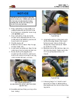
NOTE: Your machine is equipped with either
Version 1 or Version 2 of the
Hydrostatic Drive Control Handle. In
addition to difference in the
placement of controls, Version 1
allows the Parking Brake to engage/
disengage and the Ladder to extend/
retract through the Hydrostatic Drive
Control Handle (moving the handle
fully to the right). For machines
equipped with Version 2, a separate
parking brake switch is located
adjacent to the Hydrostatic Drive
Control Handle (which engages the
Parking Brake and lowers the
Ladder when activated). Refer to
specific operating instructions for
your machine.
Hydrostatic Drive Control Handle -
Version 1
•
To lower the Ladder
, move the Hydro-
static Drive Control Handle fully to the
RIGHT.
Hydrostatic Drive Control Handle -
Version 2
•
To lower the Ladder
, move the Hydro-
static Drive Control Handle to the NEU-
TRAL position.
CAUTION
Upright ladder is not a service platform
or step.
• DO NOT step on the ladder while in the
upright position.
• DO NOT lower the ladder while anyone is
on the ground near the machine.
• DO NOT attempt to lower the ladder from
ground level.
CAUTION
Ensure the Hydrostatic Drive Control
Handle is in the NEUTRAL position
before engaging the parking brake.
Failure to comply may result in personal
injury and/or machine damage.
Hydrostatic Drive Control Handle
(Version 1)
-Typical View
Summary of Contents for STS12i Combo
Page 276: ......


