IV.
OPERATING SYSTEMS
29
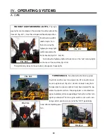
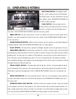
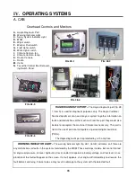
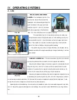
WINDSHIELD WIPER AND WASHER FLUID SWITCHES–
The windshield wiper switch (fig. 29-3,
item A) located on the right side of the headliner, turns on the wiper (fig. 29-5, item A). The wiper will continue
to operate until the switch is returned to the OFF position. Replace the 39 inch blade as necessary.
To activate the washer fluid pump, press the washer fluid switch (fig. 29-3, item B) and hold until the de-
sired amount of fluid is dispensed and then release the switch. You must turn the wiper OFF when the washer
fluid has been completely wiped away. Washer fluid reservoir is located behind the cab (fig. 29-4).
The fluid nozzle (fig. 29-5, item B) is adjustable. Check spray pattern and adjust at the beginning of each
spray season or as necessary.
FIG. 29-3
FIG 29-4
FIG 29-5
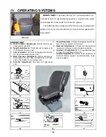
A. CAB
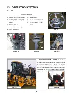
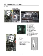
SPRAY SYSTEM INDICATOR LIGHT–
The
spray system indicator light (fig. 29-1, item A) will
illuminate when the work mode switch and the main
spray control on the hydrostatic lever (fig. 29-2) has
been activated. If the light is not on, the spray sys-
tem is not on.
MDM–
The MDM (fig. 29-1, item B) is also re-
ferred to as the message center. The MDM takes the place of the conventional gauges. This monitor can give
you information on tread adjust width, engine RPM, engine oil pressure, hour meter, fuel level, coolant tem-
perature, tire size, battery voltage, speed range, and machine program version. The information can be viewed
by using the up and down arrows to move through it. The MDM will also display any faults found in the moni-
tored systems.
FIG. 29-1
A
B
FIG. 29-2
A
B
A
B

