10-15
SECTION 10 –
MISCELLANEOUS
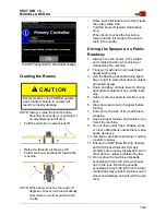
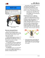
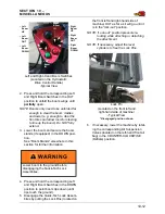
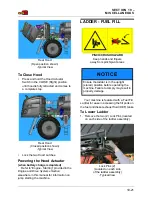
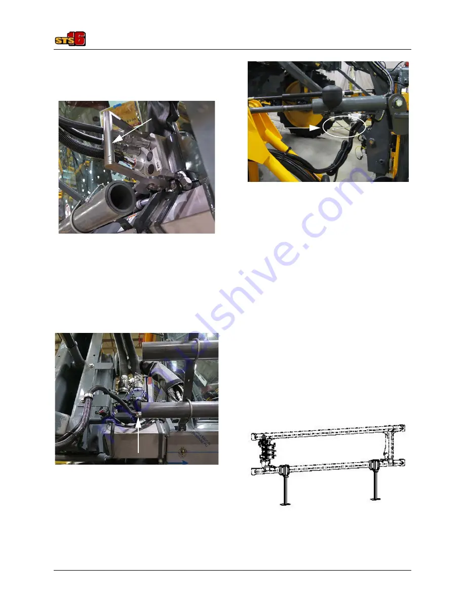
12. Push the Quick Connect Handle (located
on the Hydraulic/Electric Multi-Coupler
Assembly) IN to disengage hydraulic/
electrical connections.
13. Remove Hydraulic/Electrical Connec-
tions from the Multi-Coupler Receptacle.
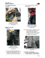
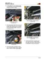
14.
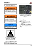
If equipped
, disconnect the Dual Prod-
uct Electrical Connection (located on the
front right-hand side of machine).
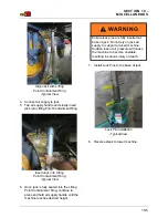
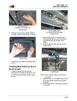
15.
If equipped
, rotate the NORAC Hand
Valve (located on the left and right-hand
level cylinders) in the CLOSED (clock-
wise) position.
16. If no other attachment is going to be
installed, re-lock the Quick-Tach Lock
Assemblies by pushing the Lock Pins IN.
17. Start the machine.
18. Disengage the parking brake and slowly
back away from the boom.
19. If the air bags were previously deflated,
raise the machine by rotating the corre-
sponding Air Suspension Valves in the
CLOCKWISE (Inflate) position.
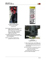
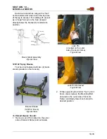
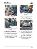
Boom Stands
90/100’ Spray Booms
Your boom is featured with three boom
stands - two (2) located on the transom and
one (1) located on each of the inner boom
sections.
Hydraulic/Electric Multi-Coupler Assembly
(Located on the front
left-hand side of machine)
• Quick
Connect
Handle
Dual Product Electrical Connection
- if equipped
(Located on the front
right-hand side of machine)
-Typical View
NORAC Hand Valve (2) -
if equipped
(Located on the left and
right-hand level cylinders)
-Typical View
* Right-hand level cylinder shown
Booms Stands
(90’ Boom)
-Typical View


