background image

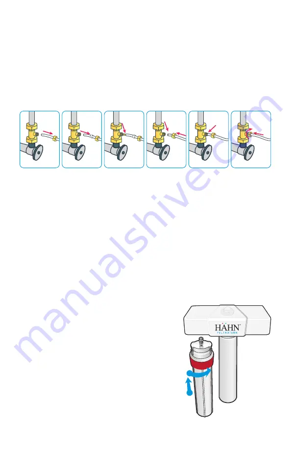
Step 1: Install Brass Fitting

1.  Turn off the cold water supply to the sink.

2.  Turn on the kitchen faucet to release pressure and allow water to drain from the line.

3.   Disconnect the cold water line from the 1/2" threaded stem on the bottom of the 

kitchen faucet. Attach threaded ends of supplied brass tee to the cold water supply 
line and shut-off valve; tighten using an adjustable wrench.

4.  Attach 1/4" white tube to the brass tee:  

A.  Slide the compression nut onto the white tubing. 
B.  Slide the plastic sleeve onto the white tube. 
C.  Place brass insert into the opening of white tube. 
D.  Push the tip of the white tubing into the opening of the brass tee. 
E.  Slide the compression nut onto the threads of the brass tee.
F.   While holding the white tube in place, tighten the compression nut to compress 

the plastic sleeve and create a seal. 

NOTE:

 Use a wrench to ensure complete seal. 

Avoid over tightening.

5.  Do not connect the other end at this time.

Step 2: Install System Manifold

1.  Select an easily accessible area under the sink to 

mount system manifold and remineralizer holder. 
You want to allow at least a 4 to 6 inch clearance 
below the filters to the floor to allow ample space 
for filter changes. To help gauge the right location 
for your system manifold, insert first and third 
stage filter sumps into manifold. Insert sumps by 
aligning top connection points and push up and to 
the right until sumps are locked in. 

2.  Mark wall placement for mounting screws using 

built-in bracket on back of manifold. Make sure 
holes are as level as possible. Mark screw place-
ment of the remineralizer holder 1 or 2 inches from 
the third stage sump to the right of the manifold. 

A

B

C

D

E

F

2

1

Summary of Contents for AquaH20 HF-RO

Page 1: ...AquaH20 Drinking Water System Owner s Manual MODEL HF RO...

Page 2: ...out G RO Faucet Body Stem stem not shown H Water Storage Tank I Eye Dropper J Tank Connector K Teflon Tape L Drain Connector M Nuts Bolts N Foam Seal O O Ring Faucet Base P Toggle Bolts Q Flow Restric...

Page 3: ...o ensure adequate space and proper positioning 3 8 white tubing will be used to connect manifold to tank and from faucet stem to remineralizer Measure out 3 8 white tubing from the top of the tank to...

Page 4: ...e tube in place tighten the compression nut to compress the plastic sleeve and create a seal NOTE Use a wrench to ensure complete seal Avoid over tightening 5 Do not connect the other end at this time...

Page 5: ...e tubing through the nut collar and sleeve into the connector B Unscrew the compression nut from the tank connector to ensure that the tubing is connected all the way through the collar and sleeve C S...

Page 6: ...k hole until faucet base is flush with countertop Position toggle bolts under sink surface being certain faucet stem will not be obstructed Loosely fasten faucet base to countertop by tightening toggl...

Page 7: ...ocation 2 Remove protective cover from back of foam seal 3 Knock center hole out align holes and attach to front plate of drain connector 4 Allowing room for drilling position the drain connector on s...

Page 8: ...ing in order to prevent crimping kinks loops or folds TUBING DONT S DO NOT cut tubing too short Always double check measurements before cutting DO NOT bend or crimp or kink tubing DO NOT discard exces...

Page 9: ...lled in step 4 from the faucet into the remineralizer port labeled OUTLET IV Manifold to Tank 3 8 white tubing already attached to tank 1 Take the white tubing leading from the storage tank and insert...

Page 10: ...ttach red carbon sump to the 1st stage position on the inlet side of the system manifold Make sure all con nection points are aligned and push the top of the sump up and into the system manifold Turn...

Page 11: ...System 2 To purge air from the plumbing system open kitchen faucet Close faucet when water runs smooth 3 Confirm RO faucet is closed 4 Within approximately 2 hours pressure will start to build in the...

Page 12: ...conditions on the above are 250 ppm TDS and a 30 6 recovery rate Production rate and TDS reduction figures are for a new Membrane that has been rinsed for 24 hours The production rate of a new Membran...

Page 13: ...rapidly convert trivalent arsenic to pentavalent arsenic Other water treatment chemicals such as ozone and potassium permanganate will also change trivalent arsenic to pentavalent arsenic A combined c...

Page 14: ...igher than 8 0 membrane life may be as short as 12 months If pH is under 7 5 membrane life may last up to 36 months When output water quality and production rate decrease it is time to replace the fil...

Page 15: ...It is recommended the restrictor assembly be periodically inspected to be sure it is clean and unrestricted If service is required on the drain flow assembly disassemble and reassemble as outlined in...

Page 16: ...ternational against NSF ANSI Standards 42 and 53 in model HF RO for the reduction claims specified on the Performance Data Sheet as verified and substantiated by test data and at nsf org The HF RO sys...

Reviews: