Page 6
ABOUT FIRE ZONES
The Omni II system supports normally open (closed for alarm), two-wire or four-wire smoke detectors. Two-wire smoke
detectors can only be connected to Zones 1-4. Four-wire smoke detectors can be connected to any zone. An external 1000-ohm
end-of-line resistor must be used for all fire (and gas) zones. When Zones 1-4 are configured as a Supervised Fire (two-wire or
four-wire) or Gas zone, the corresponding Zone Jumpers (JP11-JP14) must be in the "SMK" (smoke) position. Zone Jumper
"JP11" corresponds to Zone 1, "JP12" corresponds to Zone 2, "JP13" corresponds to Zone 3, and "JP14" corresponds to Zone 4.
1.
Smoke detectors must be powered from SWITCH 12V or an Output configured as a SWITCHED POWER OUTPUT.
2.
End of line resistor: 1000 ohms. Maximum loop resistance EXCLUDING end of line resistor is a 150 ohms. Use HAI
Model 1503A0011 End of Line Resistor Assembly in UL Listed Installations.
3.
Smoke detectors are reset when the security system is armed.
TWO-WIRE SMOKE DETECTORS
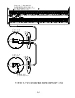
Omni II supports two-wire smoke detectors connected to Zones 1-4.
1.
Use normally open (closed for alarm) two-wire "SYSTEM" type smoke detectors (System Sensor 2100TS or equivalent),
rated 8 - 14 VDC. In UL installations, the System Sensor 2100 series 2-wire smoke detectors must be used.
2.
Smoke detectors must be connected to Zones 1-4 and configured as a Supervised Fire Zone. A maximum of 10 2-wire smoke
detectors can be connected to each zone.
3.
An external 1000-ohm end-of-line resistor must be used.
4.
Connect to the SWITCH 12V or an Output configured as a SWITCHED POWER OUTPUT.
5.
The corresponding Zone Jumpers (JP11-JP14) must be in the SMK (smoke) position.
4.
Refer to
FIGURE 3 (TWO-WIRE FIRE ZONE CONNECTIONS)
for this configuration.
Smoke detector compatibility identifier: A
FOUR-WIRE SMOKE DETECTORS
Omni II supports four-wire smoke detectors connected to any zone (1-48).
1.
Use normally open (closed for alarm) four-wire "SYSTEM" type smoke detectors (System Sensor 2112/24TR or equivalent),
rated 8 - 14 VDC.
2.
An End of Line Power Supervision Relay Module (System Sensor A77-716B or equivalent) is required for UL installations.
Install 1000-ohm end-of-line resistor as shown.
3.
Power the smoke detector from SWITCH 12V or an Output configured as a SWITCHED POWER OUTPUT.
4.
When connected to Zones 1-4, the appropriate Zone Jumper (JP11-JP14) must be in the SMK (smoke) position.
NOTE:
Smoke detectors connected to Zones 1-4 are wired differently from those connected to Zones 5-48.
Refer to
FIGURE 4 (FOUR-WIRE FIRE ZONE CONNECTIONS)
for each configuration.
Summary of Contents for OMNI II
Page 2: ......
Page 21: ...Page 15 BLACK RED RED FIGURE 7 SOUNDER CONNECTIONS...
Page 67: ......
Page 68: ...HAI New Orleans LA U S A...


